The cost of maintaining a large cutting-fluid system can be enormous. Depending on the volume of machining being performed, a shop might pay anywhere from tens of thousands to hundreds of thousands of dollars for replacement coolant, coolant additives, and downtime for coolant system cleaning and recharging. Fluid systems often need close monitoring and maintenance.
Users must add emulsifiers, oil concentrate, anticorrosion agents, and biocides to maintain the proper fluid pH and oil concentration. Disposable components must be replaced. And at the end of the fluid's useful life, end users must pay an additional expense to have the fluid waste treated and disposed of properly. Some end users say they pay as much as $1 per gallon in disposal costs.
There are indirect costs associated with the use of cutting fluids as well. Because the fluids do not remain within the work envelope of the machine tool, shops must pay for additional plant housekeeping when fluids are used. Also, maintaining worker health in the presence of potentially harmful fluid mists can be expensive. Cutting fluids can adhere to chips, making their disposal more costly. The use of fluids can adversely affect tool life and jeopardize the machine tool's reliability and useful life. And the presence of petroleum-base fluids increases the risk of fire in the shop.
To avoid these costs and problems, shops are beginning to explore dry machining. But there are costs and problems associated with this alternative as well. To make an informed decision about the use of cutting fluids, shops must understand the effects that machining without fluid will have on their operations. Researchers at Michigan Technological University (MTU), Houghton, MI, have conducted experiments to quantify these effects.
Health Concerns
Shops should be aware of cutting fluid alternatives, because safety and environmental concerns could eliminate machining with cutting fluid as an option in the near future. As health and safety regulations governing the use of cutting fluids become stricter, the cost of compliance may outweigh the benefits of cutting fluid use.
The hazards associated with cutting fluids are well documented. Because of these hazards, many cutting fluids in widespread use a mere 30 years ago, such as carbon tetrachloride, have vanished from manufacturing facilities. While the synthetic, straight, and soluble oils in use today may pose less of a direct toxic hazard than previously used chemicals, their short- and long-term effects are of major concern. For instance, direct skin contact can cause an allergic reaction or dermatitis. Inhalation of fluid aerosols can lead to immediate problems for asthma sufferers and long-term breathing disorders for those who work in the shop environment. The petroleum products that are the basis for the majority of cutting fluids are suspected carcinogens.
Even workers operating enclosed machines are exposed to fluid mists and dust present in the shop. Both the Occupational Health and Safety Administration and the United Auto Workers are backing standards that would lower the allowable amount of airborne pArticles. Under the proposed standard, levels would drop from 5.0mg/m3 to 0.5mg/m3.
But even compliance with the stricter standard might not assure worker safety. While some current air-filtration technologies reduce the overall mass concentration of suspended droplets, they also increase the concentration of the smallest aerosols. Conventional foam or fabric filters may absorb suspended droplets but then release submicron size pArticles after becoming loaded with oil. Exposure to this finer mist may be more dangerous than exposure to larger droplets. PArticles smaller than 10µm have the highest probability of being deposited in tracheobronchial airways and the pulmonary region of humans, and thus have a greater potential for adverse health effects.
To decrease the risks from smaller particulates, the Environmental Protection Agency (EPA) has recently proposed stricter standards for airborne particulate matter (PM). The current metric used for monitoring particulate matter is PM10. This means that all pArticles with a mean aerodynamic diameter less than or equal to 10µm are measured together, and the total amount of this particulate in a shop's air is stated as a single number. But a mass concentration made up of fine and ultrafine pArticles (smaller than 2.5µm in diameter) will have a greater potential for interacting with many more cells in the respiratory tract than an equivalent concentration of coarse pArticles. Because of this fact, a shop can't know how severe its contamination problem is until it knows how much of the mass concentration is composed of finer pArticles. Therefore, the EPA has proposed revising the PM monitoring metric from PM10 to PM2.5 and creating standards that would dictate a smaller mass concentration if the pArticles are 2.5µm or less in diameter.
Despite these drawbacks, shops continue to use cutting fluids because of the perceived benefits. Researchers say that the cutting fluid in a machining operation acts primarily as lubrication to reduce process friction and as a coolant to remove process-generated heat. From a practical standpoint, the cutting fluid serves other purposes as well. For instance, a stream of fluid can transport chips from the cutting zone. Recirculating fluid provides thermal stability to the frame of the machine tool. Jets of fluid wash chips and tramp oils from pockets of the bed where they may otherwise collect. And the residual cutting fluid film also provides some corrosion resistance to the machine tool and the workpiece.
More Data Is Needed
Before changing, reducing, or eliminating cutting fluids from an operation, a shop must be able to predict the good and bad consequences. Unfortunately, there is a lack of knowledge regarding the selection and application of fluids in various machining operations. An analytical fluid-selection tool does not exist, and researchers have not systematically measured or documented many of the critical thermophysical properties (such as specific heat, viscosity, density, and thermal conductivity) for the various concentrations and temperatures commonly used in metal machining.
Process designers and production engineers also lack predictive models that would tell them what process performance issues, health hazards, and environmental impacts are associated with their choice of fluid. End users cannot even find answers to basic, vital questions about cutting fluid use, and, as a result, they remain in the dark about what flow rate or fluid-application strategy to use. This confusion leads to the overuse or misuse of cutting fluids in a majority of machining operations.
Designers and engineers may rely on conventional wisdom to guide them, but research has shown that this cannot be trusted in every case. For instance, recent research has challenged the generally held belief that a flow of cutting fluid acting as coolant will either increase tool life when cutting at high speeds or permit the use of higher cutting speeds while maintaining tool life at its existing level. In these experiments, two types of medium-carbon steel were turned using two types of uncoated carbide tools
When the researchers cut the metal at speeds over 130m/min. they found that the tools experienced pronounced thermal shock when coolant was used. This shock increased crater wear slightly and significantly increased flank wear, thus decreasing tool life drastically. This phenomenon occurred with cuts lasting less than 40 sec., which reflects the duration of most production-machining operations.
Although some research, such as this study of high-speed turning, has been done, no comprehensive study on cutting fluid in machining has ever been performed. There is no body of knowledge that would compare to Frederick Taylor's studies of tool steels at the turn of the century. To expand what is known about coolant use, researchers at Michigan Tech. chose to conduct their own studies. Their work focused on characterizing the role of cutting fluids in the machining of cast-aluminum alloys. Aluminum was chosen because of its importance to the region's auto industry and because it is not susceptible to the corrosion problems ferrous materials may experience.
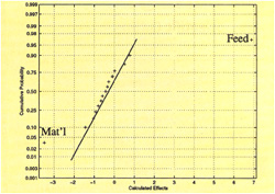
Figure 1: An example of a normal probability plot for a drilling experiment. The significance of the material and feed variables is indicated by their positions away from the main line.
Courtesy of Michigan Technical University.
Experimental Activity
Through experiments conducted over the last four ears, researchers at MTU have examined a number of processes and process variables. They used factorial design techniques to quantify the effects of different variables on a number of performance measures.
For a factorial design, the significant effects may be determined using a normal probability plot (NPP). Once all observed effects are plotted on the NPP, the majority of the effects will fall more or less along a straight line, indicating that these effects are not significant. The significant effects can then be easily identified, because they are the ones that lie off the line when they are plotted. Researchers use fractional factorial design to study a large number of variables using the results of a much smaller number of experiments.
Figure 1 shows an example of an NPP. This is a plot of a drilling experiment in which the workpiece material, cutting-fluid concentration, drill speed, and drill feed were varied to study the effects these changes would have on the average mass of the chips produced. Because the plots for feed and material are the only ones off the line, it may be surmised that these two are the significant effects for this experiment. The chip mass was not affected by changes in the soluble-oil concentration level or cutting speed, or any input interactions between these variables.
Using this factorial design, the MTU researchers examined the effects of cutting fluid on drilling. Drilling with cutting fluid produces three principal waste streams: chips, worn tools, and spent cutting fluid. Chips and tools can be recycled. Cutting fluids, on the other hand, must be treated and disposed of, and shops often must pay more for this treatment and disposal than they pay for new fluid.
To put a more scientific perspective on the use of cutting fluids in drilling, the MTU researchers conducted more than 100 statistically designed drilling tests. For the tests, the researchers used commercially available drills to produce holes in Al-308 and Al-390 samples. Some of the drills were treated with experimental coatings. The machining parameters used were within the range of parameters a shop might use for a similar operation. When cutting fluid was used, it was delivered in three jets directed at the hole to ensure that the fluid coated the cutting zone. The researchers used a variety of flow rates, all within a typical range for this type of operation. The tests were of short duration, and no evidence of wear was visible on the drills.
This research helped quantify the effect cutting fluid has on the hole's surface finish. The researchers found that the surface roughness average, Ra, was on average twice as large when the hole was drilled dry as it was when cutting fluids were used. Shops that are considering drilling aluminum without cutting fluid must take this effect into account. If the specifications call for a low Ra, then a shop will probably have to use cutting fluid despite the costs involved. However, if a hole is simply being used for clearance, this increase in roughness may not be problematic.
The research also revealed the relationship between the use of cutting fluid and the torque generated by the drilling operation. The cutting fluid lubricates the point of contact between the drill margin and the sidewall of the hole. This lubrication accounts for the reduction in torque when cutting fluids are used. In the dry-drilling tests with coated drills, the coatings duplicated the effect of the cutting fluid to some extent. However, the coatings that reduced forces the most also were the coatings that were the most easily abraded from the tool by contact with the workpiece. Other coatings did not function well in the presence of the fluid.
Dry Drilling
When the researchers varied the cutting-fluid flow rate, they found that they could use a rate two orders of magnitude less than the maximum rate without affecting process outputs. In other words, torque, thrust, and surface finish remained the same even though the cutting-fluid flow rate was significantly less than the typical rate a shop might use.
With closed-face machining processes such as drilling, cutting fluid plays a role in chip control. Controlling chips is a concern in closed-face processes because the chips are in constant intimate contact with the workpiece and tool. If they are not directed away from the cut face, they can cause damage to the machined surface.
Figure 2: As these plots indicate, the use of cutting fluid did lower torque and axial forces when AL-390 was tapped with a 1/4-20 UNC thread at 475 rpm.
Courtesy of Michigan Technical University.
Other machining processes, in addition to drilling, are commonly associated with cutting fluid use because of the close contact that occurs between the chip and the workpiece. Among these processes are broaching, sawing, and tapping. Cutting fluid is especially important for conventional internal-thread tapping, because it is particularly susceptible to failure due to excessive torque.
MTU researchers conducted a set of experiments to investigate the effects a variety of cutting-fluid applications have on internal-thread tapping. A plot of tapping torque and thrust forces with and without tapping fluids is shown in Figure 2. These results clearly show the lubricity effects of the cutting fluid.
Boring Without Coolant
By contrast, boring is an open-faced process, in which chips can be directed away from the machined surface easily. MTU researchers conducted a study to determine the importance of cutting fluid to such a process. The researchers bored Al-308 and Al-390 test castings, using a soluble-oil cutting fluid. The test variables included speed, feed, depth of cut, tool geometry/material, oil concentration, tramp-oil contamination, and the pH of the cutting fluid. Performance measures examined during the short-duration boring tests were the size of the built-up edge on the tool, the surface finish, and the cutting forces.
The results of these experiments were clear. The researchers found that none of the cutting-fluid related variables had any effect on the performance of the process. Neither the test samples' surface texture, the machining forces, nor the built-up edge appeared to be influenced by the presence or absence of cutting fluid, its degree of contamination, or the concentration used.
However, boring without coolant might alter process performance in ways that were not evaluated in this first series of experiments. For instance, this research did not address the effect that cutting fluid may have on the temperature during cutting and, thus, the fluid's ability to influence the level of thermal deformation/surface error in the part.
With this thought in mind, the MTU researchers conducted another series of tests to study the temperature in the bore during cutting as a function of cutting fluid and other variables. The measured temperatures matched those predicted by a model that describes bore temperature as a function of time, radial position, and axial position. The experimentally and analytically determined temperatures verified the coolant's ability to moderate the temperature in the workpiece before and after the tool passes a given location.
Figure 3: This graph shows the surface errors predicted by a model of a boring process. As indicated, boring without cutting fluid will result in greater errors due to the higher temperatures generated.
Courtesy of Michigan Technical University
After taking these measurements, the researchers put the bore temperature data into a finite-element model of the part to compute the bore surface errors that would be caused by the process' elevated temperatures. In Figure 3, the computed errors are plotted for the conventional-speed boring of aluminum test pieces with a 50% concentration of cutting fluid and without any fluid. As Figure 3 shows, boring with cutting fluid does result in a lower level of surface errors. The user must decide if this improvement merits the use of the cutting fluid.
The Future of Dry Machining
It should be noted that conversion to dry machining might require some alterations to workpiece specifications. Machining parameters also might require modifications, and these changes can lead to higher machining costs. For instance, in order to maintain surface-finish requirements, the user may need to reduce feedrates, and this will increase cycle time. Also, tooling costs may increase slightly because the elimination of cutting fluid may reduce tool life. However, the higher tooling costs will be offset by the elimination of cutting fluid-related costs.
End users will probably consider the possibility of machining dry in the near future, if they are not faced with the need to eliminate coolant already. There are several drawbacks to using cutting fluid, while the benefits of fluid use depend on the process and the processing conditions. In the short term, the dry/wet question must be answered on a case-by-case basis, with decision makers deciding if the advantages of cutting-fluid use outweigh the disadvantages.
About the Authors
Steve Batzer is a doctoral candidate in the Mechanical Engineer-Engineering Mechanics Department of Michigan Technological University, Houghton, MI. John Sutherland is a professor and director of graduate studies within the department.
Related Glossary Terms
- alloys
alloys
Substances having metallic properties and being composed of two or more chemical elements of which at least one is a metal.
- backing
backing
1. Flexible portion of a bandsaw blade. 2. Support material behind the cutting edge of a tool. 3. Base material for coated abrasives.
- boring
boring
Enlarging a hole that already has been drilled or cored. Generally, it is an operation of truing the previously drilled hole with a single-point, lathe-type tool. Boring is essentially internal turning, in that usually a single-point cutting tool forms the internal shape. Some tools are available with two cutting edges to balance cutting forces.
- broaching
broaching
Operation in which a cutter progressively enlarges a slot or hole or shapes a workpiece exterior. Low teeth start the cut, intermediate teeth remove the majority of the material and high teeth finish the task. Broaching can be a one-step operation, as opposed to milling and slotting, which require repeated passes. Typically, however, broaching also involves multiple passes.
- built-up edge ( BUE)
built-up edge ( BUE)
1. Permanently damaging a metal by heating to cause either incipient melting or intergranular oxidation. 2. In grinding, getting the workpiece hot enough to cause discoloration or to change the microstructure by tempering or hardening.
- clearance
clearance
Space provided behind a tool’s land or relief to prevent rubbing and subsequent premature deterioration of the tool. See land; relief.
- coolant
coolant
Fluid that reduces temperature buildup at the tool/workpiece interface during machining. Normally takes the form of a liquid such as soluble or chemical mixtures (semisynthetic, synthetic) but can be pressurized air or other gas. Because of water’s ability to absorb great quantities of heat, it is widely used as a coolant and vehicle for various cutting compounds, with the water-to-compound ratio varying with the machining task. See cutting fluid; semisynthetic cutting fluid; soluble-oil cutting fluid; synthetic cutting fluid.
- corrosion resistance
corrosion resistance
Ability of an alloy or material to withstand rust and corrosion. These are properties fostered by nickel and chromium in alloys such as stainless steel.
- cutting fluid
cutting fluid
Liquid used to improve workpiece machinability, enhance tool life, flush out chips and machining debris, and cool the workpiece and tool. Three basic types are: straight oils; soluble oils, which emulsify in water; and synthetic fluids, which are water-based chemical solutions having no oil. See coolant; semisynthetic cutting fluid; soluble-oil cutting fluid; synthetic cutting fluid.
- cutting speed
cutting speed
Tangential velocity on the surface of the tool or workpiece at the cutting interface. The formula for cutting speed (sfm) is tool diameter 5 0.26 5 spindle speed (rpm). The formula for feed per tooth (fpt) is table feed (ipm)/number of flutes/spindle speed (rpm). The formula for spindle speed (rpm) is cutting speed (sfm) 5 3.82/tool diameter. The formula for table feed (ipm) is feed per tooth (ftp) 5 number of tool flutes 5 spindle speed (rpm).
- depth of cut
depth of cut
Distance between the bottom of the cut and the uncut surface of the workpiece, measured in a direction at right angles to the machined surface of the workpiece.
- feed
feed
Rate of change of position of the tool as a whole, relative to the workpiece while cutting.
- flank wear
flank wear
Reduction in clearance on the tool’s flank caused by contact with the workpiece. Ultimately causes tool failure.
- lubricity
lubricity
Measure of the relative efficiency with which a cutting fluid or lubricant reduces friction between surfaces.
- sawing
sawing
Machining operation in which a powered machine, usually equipped with a blade having milled or ground teeth, is used to part material (cutoff) or give it a new shape (contour bandsawing, band machining). Four basic types of sawing operations are: hacksawing (power or manual operation in which the blade moves back and forth through the work, cutting on one of the strokes); cold or circular sawing (a rotating, circular, toothed blade parts the material much as a workshop table saw or radial-arm saw cuts wood); bandsawing (a flexible, toothed blade rides on wheels under tension and is guided through the work); and abrasive sawing (abrasive points attached to a fiber or metal backing part stock, could be considered a grinding operation).
- soluble-oil cutting fluid
soluble-oil cutting fluid
Fluid in which oil is suspended in water. Because water is a superior heat-removal agent, this fluid is primarily used when lubrication is desirable but cooling is the key consideration. The ratio of oils and other additives to water varies with the application. For milling, the ratio of water to oil/additives runs 20:1 to 25:1. For sawing and other work, where a more confined tool/chip/workpiece condition is normal, a 10:1 ratio is used to improve lubricity. Additives include emulsifying agents that help keep the oil in suspension and substances that promote wetting, enhance lubricity, prevent chipwelding and inhibit rusting. Also known as emulsified oil. See cutting fluid.
- surface texture
surface texture
Repetitive or random deviations from the nominal surface, which form 3-D topography of the surface. See flows; lay; roughness; waviness.
- tapping
tapping
Machining operation in which a tap, with teeth on its periphery, cuts internal threads in a predrilled hole having a smaller diameter than the tap diameter. Threads are formed by a combined rotary and axial-relative motion between tap and workpiece. See tap.
- tool steels
tool steels
Group of alloy steels which, after proper heat treatment, provide the combination of properties required for cutting tool and die applications. The American Iron and Steel Institute divides tool steels into six major categories: water hardening, shock resisting, cold work, hot work, special purpose and high speed.
- turning
turning
Workpiece is held in a chuck, mounted on a face plate or secured between centers and rotated while a cutting tool, normally a single-point tool, is fed into it along its periphery or across its end or face. Takes the form of straight turning (cutting along the periphery of the workpiece); taper turning (creating a taper); step turning (turning different-size diameters on the same work); chamfering (beveling an edge or shoulder); facing (cutting on an end); turning threads (usually external but can be internal); roughing (high-volume metal removal); and finishing (final light cuts). Performed on lathes, turning centers, chucking machines, automatic screw machines and similar machines.
- work envelope
work envelope
Cube, sphere, cylinder or other physical space within which the cutting tool is capable of reaching.