Consistently drilling a deep hole in heat-resistant stainless steel can be challenging enough. But when a workpiece is spun-cast, complexity increases because the center has a void of varying shape and size that’s created during the purification process.
“It’s the shape of a lightning bolt is the best way I can describe it,” said Tim Geyer about the spun-cast reducer that MetalTek International machines for the petrochemical industry.
The Waukesha, Wisconsin-based company is a one-stop shop for engineered products, said Geyer, senior process engineer for the machine shop and supervisor of the toolroom and programming. In addition to providing machining services, MetalTek International produces workpieces using centrifugal, sand, investment and continuous casting processes. When the company centrifugally casts a workpiece, liquid metal is poured into a die, which is spun at a specific rpm.

“It creates the Gs that force the pure metal alloys to form around the die,” he said, “and all the impurities end up inside the casting.”
The void created during casting measures about 6.35 mm to 25.4 mm (0.25" to 1") wide and 152.4 mm to 177.8 mm (6" to 7") deep, Geyer said. The drilled hole measures 74.93 mm (2.95") in diameter and 203.2 mm (8") deep.
MetalTek International does have a heat treatment facility, as well as a full chemistry laboratory. But because the part operates in a hot environment that heat-treats the part, he said the stainless steel reducer isn’t heat-treated. The part receives an initial heat treatment to anneal it, but the treatment does not increase hardness. The clean outer metal of the part has a hardness of 190 HB while the void is somewhat softer but more abrasive because of the scale that ends up there as a result of the casting process.
The company originally produced the hole with an indexable-insert drill that accepted inserts with four cutting edges, but each insert needed to be indexed two or three times to make one hole during actual production operations, Geyer said. In addition to the time that indexing consumed, the part was machined on a Warner & Swasey automatic chucker machine from the late 1960s, which moved only in one axis and didn’t have a recall function to put the head back into its previous position after a tool was extracted from a bore. This limitation meant that the machine didn’t know where it left off and therefore increased cycle time to air-cut the length drilled previously.
“Because of the abusive work that we do,” he said, “the older machines tend to provide us better results than newer machines.”
While attending a Tungaloy America Inc. seminar, Geyer became interested in the TungSix-Drill from the Arlington Heights, Illinois-based toolmaker because of the double-sided insert design with six cutting edges, which improves insert strength. Furthermore, the pocket geometry varied between the drill’s central and peripheral pocket. He also was attracted by the shape of the coolant channels, which he said delivered coolant more effectively to the face of the insert where it’s needed.
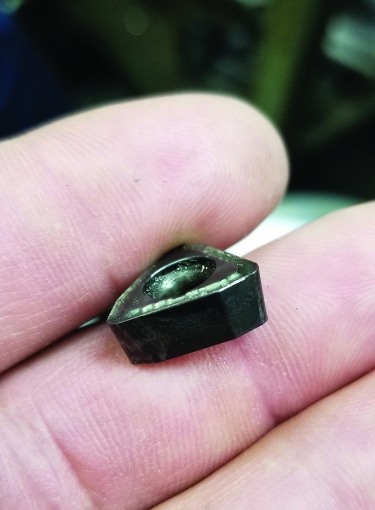
An insert from a TungSix-Drill shows wear after machining a reducer part. Image courtesy of MetalTek International
Kedar Bhagath, chief technical officer of Tungaloy America, explained that one side of the double-sided insert is for the peripheral pocket and the other is for the central pocket, which allows the chipbreaker to be optimized for the two pockets to produce the best chips. Because the cutting speed at the central pocket approaches zero toward the center axis, the chip formation is different from the chips produced by the peripheral insert.
“The most important point is that the insert corner angle in the central pocket has an obtuse angle design, which strengthens the insert and avoids insert fracture,” he said.
Bhagath said the drill’s two coolant channels are twisted with the flute shape to allow a larger chip gullet area. In addition, at the end of the channel is a slot that directs coolant toward the insert and pushes chips through the flute and out of the hole.
Geyer conducted a test to determine how the TungSix-Drill compared with the drill that MetalTek International used, as well as a drill from another cutting tool manufacturer. That third tool from a different toolmaker performed better than the original drill but had to run at about 27 m/min. (90 sfm). In comparison, the TungSix-Drill ran at a cutting speed of 52 m/min. (170 sfm) during the test. Results showed that the original drill was able to run at a cutting speed of 30 m/min. (100 sfm), a feed rate of 25 mm/min. (1 ipm), a spindle speed of 129 rpm and an operation time of 463 seconds per hole. In contrast, the TungSix-Drill ran at a feed rate of 51 mm/min. (2 ipm), a spindle speed of 220 rpm and an operation time of 273 seconds per hole while producing 24 holes.
The drill cost analysis indicated that the original drill had a $14.28 cost per drilled hole and a $13.26 machine cost per hole for a $27.54 total cost per hole. The TungSix-Drill, on the other hand, had a 45-cent drill cost per hole and a $7.80 machine cost per hole for an $8.25 total cost per hole. For the 1,000-part job, MetalTek International reduced costs by about 70% through switching to Tungaloy America’s drill.
“The total life of the job saved us about 340 hours,” Geyer said.
He described the part as a semirecurring job.
After the hole is drilled, the company performs a semifinishing pass and a finishing pass with carbide boring bars.
In addition to cost savings, the reliability of the drilling operation with the TungSix-Drill enhanced MetalTek International’s confidence that new employees could correctly perform the process, especially those on the second and third shifts, Geyer said.
“Being able to use this drill,” he said, “knowing that the inserts weren’t going to explode in the middle of the cut and knowing how many cuts we are going to get out of the insert really helped us feel comfortable that these less experienced operators running these parts will be successful in making quality parts throughout the night.”
Contact Details

Related Glossary Terms
- Brinell hardness number ( HB)
Brinell hardness number ( HB)
Number related to the applied load (usually, 500 kgf and 3,000 kgf) and to the surface area of the permanent impression made by a 10mm ball indenter. The Brinell hardness number is a calculated value of the applied load (kgf) divided by the surface area of the indentation (mm2). Therefore, the unit of measure of a Brinell hardness number is kgf/mm2, but it is always omitted.
- abrasive
abrasive
Substance used for grinding, honing, lapping, superfinishing and polishing. Examples include garnet, emery, corundum, silicon carbide, cubic boron nitride and diamond in various grit sizes.
- alloys
alloys
Substances having metallic properties and being composed of two or more chemical elements of which at least one is a metal.
- boring
boring
Enlarging a hole that already has been drilled or cored. Generally, it is an operation of truing the previously drilled hole with a single-point, lathe-type tool. Boring is essentially internal turning, in that usually a single-point cutting tool forms the internal shape. Some tools are available with two cutting edges to balance cutting forces.
- chipbreaker
chipbreaker
Groove or other tool geometry that breaks chips into small fragments as they come off the workpiece. Designed to prevent chips from becoming so long that they are difficult to control, catch in turning parts and cause safety problems.
- continuous casting
continuous casting
Casting technique in which a cast shape is continuously withdrawn through the bottom of the mold as it solidifies, so that its length is not determined by mold dimensions. Used chiefly to produce semifinished mill products such as billets, blooms, ingots, slabs and tubes.
- coolant
coolant
Fluid that reduces temperature buildup at the tool/workpiece interface during machining. Normally takes the form of a liquid such as soluble or chemical mixtures (semisynthetic, synthetic) but can be pressurized air or other gas. Because of water’s ability to absorb great quantities of heat, it is widely used as a coolant and vehicle for various cutting compounds, with the water-to-compound ratio varying with the machining task. See cutting fluid; semisynthetic cutting fluid; soluble-oil cutting fluid; synthetic cutting fluid.
- cutting speed
cutting speed
Tangential velocity on the surface of the tool or workpiece at the cutting interface. The formula for cutting speed (sfm) is tool diameter 5 0.26 5 spindle speed (rpm). The formula for feed per tooth (fpt) is table feed (ipm)/number of flutes/spindle speed (rpm). The formula for spindle speed (rpm) is cutting speed (sfm) 5 3.82/tool diameter. The formula for table feed (ipm) is feed per tooth (ftp) 5 number of tool flutes 5 spindle speed (rpm).
- feed
feed
Rate of change of position of the tool as a whole, relative to the workpiece while cutting.
- hardness
hardness
Hardness is a measure of the resistance of a material to surface indentation or abrasion. There is no absolute scale for hardness. In order to express hardness quantitatively, each type of test has its own scale, which defines hardness. Indentation hardness obtained through static methods is measured by Brinell, Rockwell, Vickers and Knoop tests. Hardness without indentation is measured by a dynamic method, known as the Scleroscope test.
Author
News items authored by Cutting Tool Engineering have been written or edited by the editors of Cutting Tool Engineering magazine. The reports represent material submitted to CTE by outside authors, and edited by CTE editors for style and accuracy.
