Courtesy of OSG Tap and Die
When the application is right, form tapping provides real production benefits.
The process of displacing metal instead of cutting it is called many things. But whether they call it form tapping, cold form tapping, thread forming, cold roll forming, roll forming, thread rolling, roll tapping or cold roll tapping, many metalworking professionals are unfamiliar with, according to Peter Gennuso, applications engineering supervisor for OSG Tap & Die Inc., Glendale Heights, Ill.
Al Zaitoon, marketing manager for YG-1 Tool Co., Vernon Hills, Ill., agreed that cut taps are more accepted and better understood. He estimates the ratio of cut taps to form taps used is about 100:1.
Form tapping requires a workpiece material that can actually flow to create the thread profile. Material with a tensile strength of 160,000 psi and a maximum hardness of 36 HRC is about the limit for form tapping, although form taps for some materials up to 40 HRC are available.
A range of metals can be form threaded, including aluminum, stainless steel, carbon steel, titanium and nickel. Brittle materials, such as cast iron, do not flow well and cannot be form tapped.
Titanium is also a challenge. “In addition to its high tensile strength and low ductility, titanium has very low thermal conductivity, meaning that it doesn’t absorb heat very well,” Gennuso said. During a tapping operation, heat enters the workpiece, tap and chips, he explained. Because forming doesn’t create chips, the heat must go into the tap or the material. When form tapping titanium, a lot of that heat penetrates the tool and causes premature failure.
Form taps are typically less than 3⁄4 ", or an M20, in diameter. Larger tools produce more friction and require more machine horsepower.
“There is also a limit on the pitch,” said Pat Nehls, product manager for Walter USA LLC, Waukesha, Wis., which offers the Protodyn CAP and Protodyn S Synchrospeed thread formers. “A fine pitch thread is easier to form because there is less material to displace. The limit is about 10 tpi, or 2.5 pitch in metric. As long as the thread profile is 10 tpi or greater, you should be able to form it.”
Hold the Chips
The biggest benefit of roll tapping is that no chips are created, eliminating chip handling and all the cleaning, maintenance and equipment it encompasses.
“In a lot of cases, depending on the material, form tapping is better for high-volume production,” OSG’s Gennuso said. “Cut tapping can cause ‘birdnesting,’ which means the operator has to stop the machine, clean out the chips and start again—repeatedly—throughout the day. The form tap can run unattended until it reaches the end of its tool life; there’s no need to pause the machining operation.”
Form tapping is particularly effective for deep-hole tapping, 3 diameters deep or more, where it can be a challenge to remove chips.
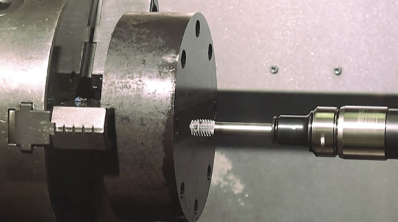
Courtesy of OSG Tap and Die
OSG’s OIL-S-XPF form tap creates threads in 4120 alloy steel bar stock used for testing. The tap can be applied in steels up to 40 HRC.
A form tap has a larger tool cross-section than a comparable cutting tap. This means form taps are more rigid and less prone to breaking. Form taps are more stable when threading than cut taps, which must have large flutes to evacuate chips. “If all the variables are in place, a form tap can outlast a cut tap 30, 40 or even 50 to 1,” YG-1’s Zaitoon said.
Formed threads are also stronger than cut threads. According to Machinery’s Handbook, that’s because the grains in the metal are unbroken in a formed thread and the displaced metal workhardens. In other words, the forming process produces the high static and dynamic tensile strength of the thread because of the workhardening.
“It has to do with the material’s grain structure,” Gennuso said. “A form tap actually compresses that grain structure to create the thread profile. That compression produces a much denser grain structure, so the threads are stronger. A cut tap disrupts that grain structure, creating a weaker thread.”
According to Walter’s Nehls, another benefit of form tapping is “better economy in the manufacturing environment. With forming, you don’t put as much wear on the tool so you can produce more threads at a lower cost per thread than with a cut tap.” Thread forming also produces threads faster than thread cutting, he added.
Machine Tool Factors
Forming taps, however, require more machining torque and the workholding must be more stable than for cut taps. According to Gennuso, form tapping takes two to four times more torque than thread cutting, so the machine has to work two to four times harder to create the thread.
The amount of torque required depends on tap size. “Our form tap sizes range from M1 to M48, but the normal usage for form taps is from M3 to M20,” said Wolfgang Ruff, vice president of engineering for KOMET of America Inc., Schaumburg, Ill. “For an M48, the part is bigger, so you will already have a bigger machine with higher torque.”
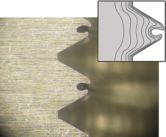
Courtesy of KOMET of America
Instead of a complete thread profile, form tapping produces a channel, or void (semicircular areas in photo), inside the thread crest.
It is important to have a machine tool that can match not only the torque, but also can operate at the feed rate form tapping requires. The machine tool has to be capable of rigid tapping, noted Thomas Sheehy, manager of applications engineering, Hardinge Inc., Elmira, N.Y.
A machine capable of rigid tapping has a tapping cycle within the control to synchronize the machine’s spindle rotation to the linear motion of the tapping axis. This allows the machine to match and maintain a specific thread pitch at all times. With rigid tapping, the linear movement of the tapping axis receives a confirmation signal from the spindle encoder to ensure that synchronization is maintained and the resulting thread conforms to specifications. Often times, this allows for faster tapping speeds and feeds compared to conventional tapping, thus improving productivity and throughput.
For machines without the capability to perform rigid tapping, tools and attachments are available to compensate. “When form tapping in a vertical machining or turning center, you can use torque limiting collets to compensate for rpm errors,” Sheehy said. “You also have a tension compression toolholder, which can provide pushback as well as pullout so you don’t run the risk of breakage. It compensates for the fact that the machine tool can’t be set to match the feed rate required for the thread pitch.”
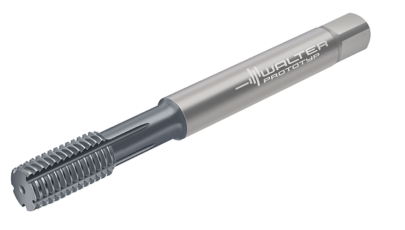
Courtesy of Walter USA
Walter Prototyp’s Protodyn S HSS-E thread former for blind- and through-holes is available in sizes M1 to M24.
A key hindrance to form tapping is that formed threads are not accepted in some industries. “The reason is because of the thread profile of a formed thread,” Gennuso said. “Instead of a complete thread profile, you get a little channel, or void, inside the thread crest that can hold contaminants. Industries such as medical and food have strict regulations regarding cleanliness, so they cannot accept threads with those channels.”
Another limiting factor to form tapping is the drilled hole has to be much more precise than for cut tapping. For an M4 standard thread, a 0.130 "-dia. hole with a +0.005 "/-0.002 " tolerance is acceptable, Nehls explained, but to form tap that thread, a 0.1457 "-dia. hole with a tighter tolerance of ±0.0012 " is required.
According to Nehls, if the drilled hole is too large, there won’t be enough material to displace to completely form the thread. If the hole is too small, there will be too much material to displace, causing part failure.
Aerospace is another industry that may restrict acceptance of form threads due to tight-tolerance requirements. “It is much more difficult to control the size of the thread with a form tap than a cut tap,” Gennuso said. “Because form taps rely on a material’s own elasticity to create the thread, formed threads are a little bit more susceptible to material expansion and shrinkage. This makes it sometimes a little bit harder to hold very tight tolerances with form taps. To compensate for this, form taps commonly utilize a larger pitch-diameter limit than cut taps; for example, a ¼-20 2B form tap would utilize an H6 limit, while a ¼-20 2B cut tap would utilize an H5 limit.”
While there’s agreement that the aerospace industry does have restrictions on form threads, everyone doesn’t agree that it is a tolerance issue. The same tolerances can be achieved with a cut tap, form tap or thread mill, according to KOMET’s Ruff. “The aerospace industry does not accept form threads due to the resulting small gap at the tip of the minor thread diameter, which can hold contamination,” he said. “The aim in aerospace is to reduce all areas of contamination.”
Still others don’t believe contamination is the issue, but indicate the aerospace industry considers that gap, or void, a possible fracture point.
Cool Off
Coolant is especially crucial when forming threads rather than cutting them because the process needs coolant to remove heat and to move the material, noted Julian Webb, KOMET product manager. Although not ideal, a thread can be cut dry and the tool will not easily break, but a forming tap run without coolant will break, according to Webb.
“There is also a difference with the coolant, depending on what type of material is being form tapped,” Webb said. “If it is a higher strength material, then you should use oil. If it is a lower strength material, a typical emulsion will work.”
Courtesy of KOMET of America
KOMET’s MOREX R HSS-E roll form taps have a flexible tool body to compensate for small misalignments, especially on transfer lines, and brazed carbide strips for rigidity.
In addition, coolant is more important when forming than cutting because there is more pressure at the tool/workpiece interface. Coolant that functions at a higher pressure is necessary. “If you use a water-based coolant, then you need an extreme-pressure additive that chemically doesn’t break down under high pressure,” YG-1’s Zaitoon said. “If you don’t use oil or an EP additive, it can put too much stress on the thread and you could get cracks.”
Form taps have some differences in the coolant delivery method. “Coolant-through taps have a hole through the center of the tap that supplies coolant directly to the forming zone. Solid taps have grooves, say 0.020 " to 0.040 " radius, that are ground into the tap itself to allow flood coolant to work its way down to the bottom of the hole,” OSG’s Gennuso said. “Regardless of the delivery method, the use of coolant is imperative in form tapping to provide effective lubrication and heat suppression.”
While some may still be unfamiliar with form tapping, those in the electronics industry aren’t. The automobile industry is also getting up to speed with form tapping, especially on aluminum parts.
To decide, ask if the application of the final part lends itself to forming, recommends Walter’s Nehls. “Do you have the machine and fixtures to do it, and do you want to take the time and effort to drill the high-quality hole needed to make the thread properly?” CTE
About the Author: Susan Woods is a contributing editor for CTE. Contact her at (224) 225-6120 or susanw@jwr.com.
Contributors
Hardinge Inc.
(800) 843-8801
www.hardinge.com
KOMET of America Inc.
(847) 923-8400
www.komet.com
OSG Tap and Die Inc.
(800) 837-2223
www.osgtool.com
Walter USA LLC
(800) 945-5554
www.walter-tools.com/us
YG-1 Tool Co.
(800) 765-8665
www.yg1usa.com
Related Glossary Terms
- coolant
coolant
Fluid that reduces temperature buildup at the tool/workpiece interface during machining. Normally takes the form of a liquid such as soluble or chemical mixtures (semisynthetic, synthetic) but can be pressurized air or other gas. Because of water’s ability to absorb great quantities of heat, it is widely used as a coolant and vehicle for various cutting compounds, with the water-to-compound ratio varying with the machining task. See cutting fluid; semisynthetic cutting fluid; soluble-oil cutting fluid; synthetic cutting fluid.
- ductility
ductility
Ability of a material to be bent, formed or stretched without rupturing. Measured by elongation or reduction of area in a tensile test or by other means.
- emulsion
emulsion
Suspension of one liquid in another, such as oil in water.
- extreme pressure additives ( EP)
extreme pressure additives ( EP)
Cutting-fluid additives (chlorine, sulfur or phosphorus compounds) that chemically react with the workpiece material to minimize chipwelding. Good for high-speed machining. See cutting fluid.
- feed
feed
Rate of change of position of the tool as a whole, relative to the workpiece while cutting.
- flutes
flutes
Grooves and spaces in the body of a tool that permit chip removal from, and cutting-fluid application to, the point of cut.
- hardness
hardness
Hardness is a measure of the resistance of a material to surface indentation or abrasion. There is no absolute scale for hardness. In order to express hardness quantitatively, each type of test has its own scale, which defines hardness. Indentation hardness obtained through static methods is measured by Brinell, Rockwell, Vickers and Knoop tests. Hardness without indentation is measured by a dynamic method, known as the Scleroscope test.
- metalworking
metalworking
Any manufacturing process in which metal is processed or machined such that the workpiece is given a new shape. Broadly defined, the term includes processes such as design and layout, heat-treating, material handling and inspection.
- milling machine ( mill)
milling machine ( mill)
Runs endmills and arbor-mounted milling cutters. Features include a head with a spindle that drives the cutters; a column, knee and table that provide motion in the three Cartesian axes; and a base that supports the components and houses the cutting-fluid pump and reservoir. The work is mounted on the table and fed into the rotating cutter or endmill to accomplish the milling steps; vertical milling machines also feed endmills into the work by means of a spindle-mounted quill. Models range from small manual machines to big bed-type and duplex mills. All take one of three basic forms: vertical, horizontal or convertible horizontal/vertical. Vertical machines may be knee-type (the table is mounted on a knee that can be elevated) or bed-type (the table is securely supported and only moves horizontally). In general, horizontal machines are bigger and more powerful, while vertical machines are lighter but more versatile and easier to set up and operate.
- pitch
pitch
1. On a saw blade, the number of teeth per inch. 2. In threading, the number of threads per inch.
- tap
tap
Cylindrical tool that cuts internal threads and has flutes to remove chips and carry tapping fluid to the point of cut. Normally used on a drill press or tapping machine but also may be operated manually. See tapping.
- tapping
tapping
Machining operation in which a tap, with teeth on its periphery, cuts internal threads in a predrilled hole having a smaller diameter than the tap diameter. Threads are formed by a combined rotary and axial-relative motion between tap and workpiece. See tap.
- tensile strength
tensile strength
In tensile testing, the ratio of maximum load to original cross-sectional area. Also called ultimate strength. Compare with yield strength.
- thread rolling
thread rolling
Chipless, cold-forming material-displacement process where a rolling head is pressed into the workpiece to create threads. The material is stressed beyond its yield point, which causes it to be deformed platically and permanently. There are three basic types of rolling heads: axial, radial and tangential.
- threading
threading
Process of both external (e.g., thread milling) and internal (e.g., tapping, thread milling) cutting, turning and rolling of threads into particular material. Standardized specifications are available to determine the desired results of the threading process. Numerous thread-series designations are written for specific applications. Threading often is performed on a lathe. Specifications such as thread height are critical in determining the strength of the threads. The material used is taken into consideration in determining the expected results of any particular application for that threaded piece. In external threading, a calculated depth is required as well as a particular angle to the cut. To perform internal threading, the exact diameter to bore the hole is critical before threading. The threads are distinguished from one another by the amount of tolerance and/or allowance that is specified. See turning.
- tolerance
tolerance
Minimum and maximum amount a workpiece dimension is allowed to vary from a set standard and still be acceptable.
- toolholder
toolholder
Secures a cutting tool during a machining operation. Basic types include block, cartridge, chuck, collet, fixed, modular, quick-change and rotating.
- turning
turning
Workpiece is held in a chuck, mounted on a face plate or secured between centers and rotated while a cutting tool, normally a single-point tool, is fed into it along its periphery or across its end or face. Takes the form of straight turning (cutting along the periphery of the workpiece); taper turning (creating a taper); step turning (turning different-size diameters on the same work); chamfering (beveling an edge or shoulder); facing (cutting on an end); turning threads (usually external but can be internal); roughing (high-volume metal removal); and finishing (final light cuts). Performed on lathes, turning centers, chucking machines, automatic screw machines and similar machines.
- workhardening
workhardening
Tendency of all metals to become harder when they are machined or subjected to other stresses and strains. This trait is particularly pronounced in soft, low-carbon steel or alloys containing nickel and manganese—nonmagnetic stainless steel, high-manganese steel and the superalloys Inconel and Monel.
 ARTICLES