The technology hasn’t hit the marketplace yet, but current research indicates that cryogenic cooling offers a way to improve tool wear resistance and efficiency in the turning of difficult-to-machine materials. For the last three years, we at the University of Nebraska-Lincoln have been working on ways to economically and efficiently turn difficult materials such as titanium-aluminum-vanadium (Ti-6Al-4V) and reaction-bonded silicon nitride (RBSN) using cryogenics. Ti-6Al-4V’s excellent mechanical properties have made it the most commonly used titanium alloy in the aerospace industry. It can be heat-treated to strengths in excess of 1.75105 psi. The alloy is stable up to a temperature of about 540° C. However, it also has low thermal conductivity (about 15 W/m2 °C). As a result, high temperature gradients are experienced in the chip/tool interface during turning operations. Titanium also is chemically reactive and, hence, tends to weld to the tool during machining. These properties accelerate tool wear. Various strategies have been implemented to combat these problems. Advanced cutting tool materials such as coated carbides, ceramics, cermets, polycrystalline cubic boron nitride (PCBN), silicon nitride, and polycrystalline diamond have offered little improvement in the material-removal rate of titanium alloys. Likewise, high-speed machining of titanium alloys has been attempted with little success. High-speed machining merely elevates the extreme temperature gradients and, hence, accelerates tool wear. Nontraditional machining methods also have been tried, including electrochemical machining, pulse electrochemical machining, chemical milling, and laser cutting. These methods have yielded low metal-removal rates and have caused pitting and thermal damage to titanium-alloy workpieces. RBSN also offers many engineering properties at levels not found in other ceramics or refractory materials (Table 1). Among these properties are high strength even at 1400° C, low thermal expansion, excellent shock resistance, and chemical inertness. However, like Ti-6Al-4V, RBSN has very low thermal conductivity. That, plus its high strength, makes RBSN extremely difficult to machine. The material causes excessive tool wear. And, like Ti-6Al-4V, the cutting methods tried so far have not yielded satisfactory results.
Properties of RBSN
| Density | 2.4 gm/cc | Fracture toughness | 3.4 MPa m1/2 | |
| Grain Size | 0.75um | Hardness | Rc60 | |
| Tensile strength | 18ksi | Young's modulus | 172.22 GPa | |
| Compressive strength | 105ksi | Thermal conductivity | 13 W/m2°C |
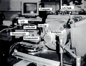 Figure 1: A cryogenically cooled turning system |
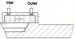 Figure 2: Turning with cryogenic cooling |
A New System
These special materials present special machining difficulties that must be overcome with the help of special technology. Our research team has designed and built a cryogenic cooling system (patent pending) that transports cryogenically cooled liquid nitrogen from a tank to a reservoir located near the rear of the cutting insert. This experimental system includes a temperature-measurement system, a force-measurement system, a data-acquisition system, and appropriate amplifiers and A/D converters (Figure 1). The cooling system’s main component is the tool cover, a metal cap designed so that the liquid nitrogen comes in close contact with the insert cutting edge. The cap is mounted on the toolholder by screws. Standard toolholders suffice, though before conducting the experiments we had to refine the toolholder’s surface to fit the cap. In all our tests, the security of the insert in the toolholder was not a problem, because the cap itself acts as a strong clamping plate on the insert. With proper sealing, the cap’s bottom edge is compressed tightly onto the insert surface. The cap’s cover has two taps on its top surface. The tap close to the tool bit is used as the inlet for the liquid nitrogen, and the other tap is the outlet. Soft copper tubes circulate the liquid nitrogen. The valve in the outlet tap of the liquid-nitrogen cylinder regulates the flow through the system (Figure 2). The liquid nitrogen is provided by a cylinder with regulators that can control the flow and pressure in the system. The cylinder is placed close to the lathe. The liquid nitrogen is in actual contact with the insert and the toolholder. When the system is working, most of the insert’s surface is in direct contact with the liquid-nitrogen coolant. The liquid-nitrogen flow starts from the cylinder. It continuously flows through a valve, a pipeline, and finally through the inlet to the cap. After cooling the insert, it flows through the outlet to another pipeline and then either sprays into the air or goes to another cylinder. The liquid-nitrogen flow should start before cutting begins. The cooling system has little effect on the dimensions of the cut, so long as the cutting tool is adjusted after the cooling circulation becomes stable. However, if the tool is adjusted before turning on the cooling system, the DOC will change. The system is designed for commercial use. It is flexible, inexpensive, and stable. However, to fit the system into a specific machine tool, the user needs to consider some details, such as the space available on the machine to arrange the positions for inlet and outlet of the liquid nitrogen. The cost of the liquid nitrogen itself is about $0.30 to $0.50 per liter. The greatest advantage in this regard is the fact that the liquid nitrogen is recyclable. It’s also quite safe, though some safety precautions should be taken when handling liquid nitrogen. Do not vigorously shake the cylinder, and do not leave the cylinder near fire or chemical fluids.
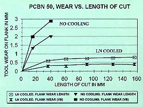 Figure 3: Wear of a PCBN tool in turning RBSN. |
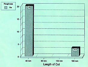 Figure 4: Surface roughness in turning RBSN. |
Lower Wear
Our tests revealed that cryogenic cooling of the insert reduced tool wear significantly compared to other cooling methods and dry machining. We conducted numerous experiments involving the turning of RBSN with PCBN 50 inserts (the typical choice of insert grade for RBSN). The tests compared dry turning of this material to cryogenically cooled turning.
We also ran tests turning Ti-6Al-4V with H-13A-grade cemented carbide inserts (again, the typical grade choice for this alloy). These tests were run with oil and with cryogenic coolant.
For both materials, a substantial improvement in tool wear and surface quality was observed when the cryogenic system was employed. Figure 3 illustrates the tool wear exhibited in the turning of a cylindrical 80mm580mm bar of RBSN with a PCBN 50 insert at the following parameters: speed, 840 rpm; feed rate, 0.004 ipr; DOC, 0.0195"; rake angle, g0=-6°; inclination angle, ls=-6°; clearance angle, a0=6°; and nose radius, 0.31".
The parameters for all the experiments were recommended by Sandvik Coromant Co. The machine used in the experiment was a Clausing Colchester 15 lathe. Run dry, the tool’s wear increased rapidly as the length of cut increased. But with liquid-nitrogen cooling, tool wear increased so slowly that even at more than 10 times the original length of cut, the tool wear was still a quarter of that without liquid-nitrogen cooling. The resulting surface roughness of the RBSN was 3.2µm Ra when the liquid nitrogen was used, compared to the 20µm Ra achieved in the dry operation (Figure 4). This discrepancy becomes more noteworthy when one considers the fact that surface roughness for the non-cooled tools was measured after 40mm, as opposed to 160mm for the liquid-nitrogen-cooled tools.
Figure 5 shows the results of turning Ti-6Al-4V with an H-13A cemented carbide insert at the following parameters: speed, 840 rpm; feed, 0.008 ipr; DOC, 0.0195"; rake angle, g0=0°; inclination angle, ls=0°; clearance angle, a0=7°; and nose radius, 0.31". Each point in the graph corresponds to the wear measurement after each cut. Cuts ranged from 5" to 8 1/2" in circumferential length. When machining was done with oil coolant, the tool wear measured 0.042" after machining a circumferential length of 11.47".
When machining was performed at the same parameters using liquid-nitrogen coolant, the tool wear was only 0.008" after machining a circumferential length of 13.85", that is, one full cut plus 2.38" of another cut. With liquid-nitrogen coolant, the tool could machine a circumferential length of 34.42" before exhibiting as much wear as an oil-cooled tool did after only one full 11.47" cut.
It appears that lowering the temperature of the insert reduced tool wear when machining Ti-6Al-4V or RBSN. When machining Ti-6Al-4V, the lower temperature reduced chemical reactivity between the work material and the tool. For both work materials, the lower temperature prevented softening of the insert material.
Lower Temperatures
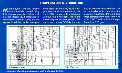
But to what extent does liquid nitrogen really lower cutting temperatures? Our experiments revealed that the cryogenic cooling system dramatically reduced the temperature of the cutting insert during the cutting process. The temperatures measured using a thermocouple at 0.079" from the PCBN 50 tool’s edge in machining both RBSN and Ti-6Al-4V with oil and liquid nitrogen are shown in Figures 6 and 7.
Figure 6 shows the cutting temperature for the tool that cut RBSN using liquid nitrogen for five cuts totaling 160mm in circumferential length, a tool run without liquid nitrogen for one 40mm-long cut, and another tool run without liquid nitrogen for two cuts totaling 40mm in length.
Tool temperature increased with the cutting time when liquid-nitrogen coolant was not used. When the tool was used for a second cut, the temperature increased at a much higher rate than in the first cut because of the increased tool wear. When the turning process was subjected to liquid-nitrogen coolant, the measured temperature (-160° to -170° C) remained almost constant. Without liquid-nitrogen coolant, PCBN 50 tools didn’t last long enough to be practical for the turning of RBSN.
Figure 7 depicts cutting temperatures measured in the machining of Ti-6Al-4V. A maximum of about 210° C was measured when oil coolant was used, as opposed to a peak value of 120° C with liquid-nitrogen coolant. It should be noted that a red-hot chip formed during machining contacted the thermocouple wire (not the junction), and this may have affected the readings. There are two peaks, one close to the 3-second mark and the other close to the 10-second mark. Peaks occurred in the same region for both liquid-nitrogen- and oil-cooled machining. This was caused by the workpiece’s surface profile. The hardness of the workpiece on both ends of the cut is slightly higher than the hardness in the middle part of the workpiece. That’s because the workpiece’s profile causes the temperature to drop much faster on either end than it does in the middle. The same trend can be seen in the force measurements.
Our testing of liquid-nitrogen cooling in turning operations continues. This technology promises to offer a practical solution to shops that deal with certain problematic work materials.
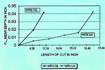 Figure 5: Wear of a carbide tool in turning Ti-6Al-4V. |
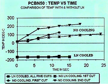 Figure 6: Temperatures measured in turning RBSN. |
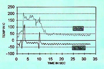 Figure 7: Temperatures measured in turning Ti-6Al-4V. |
About the Authors
K.P. Rajurkar is Mohr professor of engineering and director of the Nontraditional Manufacturing Research Center at the University of Nebraska-Lincoln. Z.Y. Wang is a research assistant professor at the center.
Related Glossary Terms
- alloys
alloys
Substances having metallic properties and being composed of two or more chemical elements of which at least one is a metal.
- ceramics
ceramics
Cutting tool materials based on aluminum oxide and silicon nitride. Ceramic tools can withstand higher cutting speeds than cemented carbide tools when machining hardened steels, cast irons and high-temperature alloys.
- cermets
cermets
Cutting tool materials based mostly on titanium carbonitride with nickel and/or cobalt binder. Cermets are characterized by high wear resistance due to their chemical and thermal stability. Cermets are able to hold a sharp edge at high cutting speeds and temperatures, which results in exceptional surface finish when machining most types of steels.
- clearance
clearance
Space provided behind a tool’s land or relief to prevent rubbing and subsequent premature deterioration of the tool. See land; relief.
- coolant
coolant
Fluid that reduces temperature buildup at the tool/workpiece interface during machining. Normally takes the form of a liquid such as soluble or chemical mixtures (semisynthetic, synthetic) but can be pressurized air or other gas. Because of water’s ability to absorb great quantities of heat, it is widely used as a coolant and vehicle for various cutting compounds, with the water-to-compound ratio varying with the machining task. See cutting fluid; semisynthetic cutting fluid; soluble-oil cutting fluid; synthetic cutting fluid.
- cubic boron nitride ( CBN)
cubic boron nitride ( CBN)
Crystal manufactured from boron nitride under high pressure and temperature. Used to cut hard-to-machine ferrous and nickel-base materials up to 70 HRC. Second hardest material after diamond. See superabrasive tools.
- cutting tool materials
cutting tool materials
Cutting tool materials include cemented carbides, ceramics, cermets, polycrystalline diamond, polycrystalline cubic boron nitride, some grades of tool steels and high-speed steels. See HSS, high-speed steels; PCBN, polycrystalline cubic boron nitride; PCD, polycrystalline diamond.
- electrochemical machining ( ECM)
electrochemical machining ( ECM)
Operation in which electrical current flows between a workpiece and conductive tool through an electrolyte. Initiates a chemical reaction that dissolves metal from the workpiece at a controlled rate. Unlike with traditional cutting methods, workpiece hardness is not a factor, making ECM suitable for difficult-to-machine materials. Takes such forms as electrochemical grinding, electrochemical honing and electrochemical turning.
- feed
feed
Rate of change of position of the tool as a whole, relative to the workpiece while cutting.
- fracture toughness
fracture toughness
Critical value (KIC) of stress intensity. A material property.
- gang cutting ( milling)
gang cutting ( milling)
Machining with several cutters mounted on a single arbor, generally for simultaneous cutting.
- hardness
hardness
Hardness is a measure of the resistance of a material to surface indentation or abrasion. There is no absolute scale for hardness. In order to express hardness quantitatively, each type of test has its own scale, which defines hardness. Indentation hardness obtained through static methods is measured by Brinell, Rockwell, Vickers and Knoop tests. Hardness without indentation is measured by a dynamic method, known as the Scleroscope test.
- inclination angle
inclination angle
Angle that the cutter edge makes with a plane that is perpendicular to the direction of tool travel. Determines the direction the chip curls.
- lathe
lathe
Turning machine capable of sawing, milling, grinding, gear-cutting, drilling, reaming, boring, threading, facing, chamfering, grooving, knurling, spinning, parting, necking, taper-cutting, and cam- and eccentric-cutting, as well as step- and straight-turning. Comes in a variety of forms, ranging from manual to semiautomatic to fully automatic, with major types being engine lathes, turning and contouring lathes, turret lathes and numerical-control lathes. The engine lathe consists of a headstock and spindle, tailstock, bed, carriage (complete with apron) and cross slides. Features include gear- (speed) and feed-selector levers, toolpost, compound rest, lead screw and reversing lead screw, threading dial and rapid-traverse lever. Special lathe types include through-the-spindle, camshaft and crankshaft, brake drum and rotor, spinning and gun-barrel machines. Toolroom and bench lathes are used for precision work; the former for tool-and-die work and similar tasks, the latter for small workpieces (instruments, watches), normally without a power feed. Models are typically designated according to their “swing,” or the largest-diameter workpiece that can be rotated; bed length, or the distance between centers; and horsepower generated. See turning machine.
- mechanical properties
mechanical properties
Properties of a material that reveal its elastic and inelastic behavior when force is applied, thereby indicating its suitability for mechanical applications; for example, modulus of elasticity, tensile strength, elongation, hardness and fatigue limit.
- milling
milling
Machining operation in which metal or other material is removed by applying power to a rotating cutter. In vertical milling, the cutting tool is mounted vertically on the spindle. In horizontal milling, the cutting tool is mounted horizontally, either directly on the spindle or on an arbor. Horizontal milling is further broken down into conventional milling, where the cutter rotates opposite the direction of feed, or “up” into the workpiece; and climb milling, where the cutter rotates in the direction of feed, or “down” into the workpiece. Milling operations include plane or surface milling, endmilling, facemilling, angle milling, form milling and profiling.
- nontraditional machining
nontraditional machining
Variety of chemical, electrical, mechanical and thermal processes for machining workpieces. Originally applied to new or emerging processes, it designates any process developed since 1945.
- pitting
pitting
Localized corrosion of a metal surface, confined to a point or small area, that takes the form of cavities.
- polycrystalline cubic boron nitride ( PCBN)
polycrystalline cubic boron nitride ( PCBN)
Cutting tool material consisting of polycrystalline cubic boron nitride with a metallic or ceramic binder. PCBN is available either as a tip brazed to a carbide insert carrier or as a solid insert. Primarily used for cutting hardened ferrous alloys.
- polycrystalline cubic boron nitride ( PCBN)2
polycrystalline cubic boron nitride ( PCBN)
Cutting tool material consisting of polycrystalline cubic boron nitride with a metallic or ceramic binder. PCBN is available either as a tip brazed to a carbide insert carrier or as a solid insert. Primarily used for cutting hardened ferrous alloys.
- polycrystalline diamond ( PCD)
polycrystalline diamond ( PCD)
Cutting tool material consisting of natural or synthetic diamond crystals bonded together under high pressure at elevated temperatures. PCD is available as a tip brazed to a carbide insert carrier. Used for machining nonferrous alloys and nonmetallic materials at high cutting speeds.
- rake
rake
Angle of inclination between the face of the cutting tool and the workpiece. If the face of the tool lies in a plane through the axis of the workpiece, the tool is said to have a neutral, or zero, rake. If the inclination of the tool face makes the cutting edge more acute than when the rake angle is zero, the rake is positive. If the inclination of the tool face makes the cutting edge less acute or more blunt than when the rake angle is zero, the rake is negative.
- tap
tap
Cylindrical tool that cuts internal threads and has flutes to remove chips and carry tapping fluid to the point of cut. Normally used on a drill press or tapping machine but also may be operated manually. See tapping.
- tensile strength
tensile strength
In tensile testing, the ratio of maximum load to original cross-sectional area. Also called ultimate strength. Compare with yield strength.
- toolholder
toolholder
Secures a cutting tool during a machining operation. Basic types include block, cartridge, chuck, collet, fixed, modular, quick-change and rotating.
- turning
turning
Workpiece is held in a chuck, mounted on a face plate or secured between centers and rotated while a cutting tool, normally a single-point tool, is fed into it along its periphery or across its end or face. Takes the form of straight turning (cutting along the periphery of the workpiece); taper turning (creating a taper); step turning (turning different-size diameters on the same work); chamfering (beveling an edge or shoulder); facing (cutting on an end); turning threads (usually external but can be internal); roughing (high-volume metal removal); and finishing (final light cuts). Performed on lathes, turning centers, chucking machines, automatic screw machines and similar machines.
- wear resistance
wear resistance
Ability of the tool to withstand stresses that cause it to wear during cutting; an attribute linked to alloy composition, base material, thermal conditions, type of tooling and operation and other variables.