Coatings for metalcutting tools have made tremendous advances since their introduction more than 40 years ago. As coatings have improved, our understanding of their behavior in a variety of cutting operations has increased, and this has led to further developments to enhance performance.
A technology that has made big strides in the past few years is post-coating treatment. As thicker coatings were developed and Al2O3coatings came into the industry, these treatments began as efforts to smooth the coating surface of CVD coatings. People observed that a smooth coating surface enhanced tool life by reducing both friction and the tendency of workpiece material to stick to the surface, which causes built-up edge. This could be called the first generation of post-coating treatment.
The surface-smoothing process is a light grit-blasting operation that removes the roughness caused by uneven coating-grain growth. Only a tiny amount of coating is removed. As these blasting processes have become more controlled, it has become possible to accurately remove a very thin layer. An example is removal of the “flash” TiN coating layer on the rake surface of an indexable insert. The advantage of the process is that it provides a smooth top surface, leaving a gold TiN layer on the flank for easy wear detection. This process could be called the second generation of post-coating treatment.
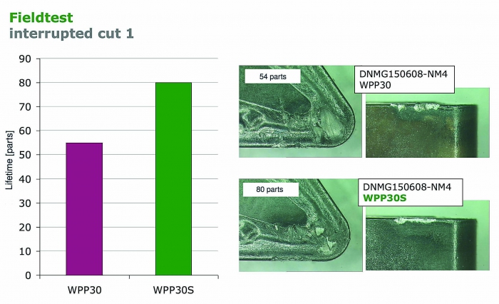
Wear on a coated insert after interrupted cutting of 54 parts (top), and wear on the same type of coated insert, but with a post-coating treatment, after interrupted cutting of 80 parts. Image courtesy of Walter USA.
Sometimes during coating, particularly during CVD processes, the coating layers can experience tensile stress. This state is caused by differences in the thermal expansion coefficients of carbide substrates and hard coating layers. A tensile-stress state can cause flaws in the coating to grow into cracks. It also tends to cause those cracks to further expand until they result in failure of the cutting edge. Most often, these cracks are generated from the stresses of the cutting operation, especially interrupted cuts.
Because coatings are ceramic materials, they are inherently weak at resisting tensile stresses but incredibly strong at resisting compressive stresses. Cracks and other flaws are unable to grow in a compressive-stress state. As second-generation treatments have been improved and controlled, it has became apparent that blasting has had the further beneficial effect of reducing the tensile stresses in CVD coatings.
Moreover, the continued development and control of many parameters in post-coating treatments has made it possible to replace tensile stresses with compressive stresses. This has led to significant improvements in the failure resistance of the cutting edge due to chipping, especially in interrupted cutting.
Because cracks are generated two ways in milling, the biggest benefits are for milling inserts. One way is from the impact that occurs every time the cutting edge enters the cut. The other way is from thermal cycling when the cutting edge heats up quickly during cutting and then cools as it exits the cut, creating thermal cracks. By having compressive stresses in the coating, the impacts and thermal cycling have to overcome the compression and then grow tensile stresses to the point at which cutting edge failure can begin.
By having compressive stresses, it takes far more cutting time and stresses to generate cracks big enough to damage the cutting edge. The increase in cutting edge life is often 30 percent or more, especially in applications involving heavy impacts and high speeds.
The figure shows a heavily interrupted camshaft turning operation with a 48 percent increase in tool life by resisting chipping of the cutting edge. These results are from the latest generation of post-coating treatments. These treatments create compressive stresses through the entire coating structure and even extend into the substrate, significantly increasing chipping resistance.
See also "Understanding coatings and how they lower machining costs."
Contact Details

Related Glossary Terms
- built-up edge ( BUE)
built-up edge ( BUE)
1. Permanently damaging a metal by heating to cause either incipient melting or intergranular oxidation. 2. In grinding, getting the workpiece hot enough to cause discoloration or to change the microstructure by tempering or hardening.
- chemical vapor deposition ( CVD)
chemical vapor deposition ( CVD)
High-temperature (1,000° C or higher), atmosphere-controlled process in which a chemical reaction is induced for the purpose of depositing a coating 2µm to 12µm thick on a tool’s surface. See coated tools; PVD, physical vapor deposition.
- gang cutting ( milling)
gang cutting ( milling)
Machining with several cutters mounted on a single arbor, generally for simultaneous cutting.
- indexable insert
indexable insert
Replaceable tool that clamps into a tool body, drill, mill or other cutter body designed to accommodate inserts. Most inserts are made of cemented carbide. Often they are coated with a hard material. Other insert materials are ceramic, cermet, polycrystalline cubic boron nitride and polycrystalline diamond. The insert is used until dull, then indexed, or turned, to expose a fresh cutting edge. When the entire insert is dull, it is usually discarded. Some inserts can be resharpened.
- metalcutting ( material cutting)
metalcutting ( material cutting)
Any machining process used to part metal or other material or give a workpiece a new configuration. Conventionally applies to machining operations in which a cutting tool mechanically removes material in the form of chips; applies to any process in which metal or material is removed to create new shapes. See metalforming.
- milling
milling
Machining operation in which metal or other material is removed by applying power to a rotating cutter. In vertical milling, the cutting tool is mounted vertically on the spindle. In horizontal milling, the cutting tool is mounted horizontally, either directly on the spindle or on an arbor. Horizontal milling is further broken down into conventional milling, where the cutter rotates opposite the direction of feed, or “up” into the workpiece; and climb milling, where the cutter rotates in the direction of feed, or “down” into the workpiece. Milling operations include plane or surface milling, endmilling, facemilling, angle milling, form milling and profiling.
- rake
rake
Angle of inclination between the face of the cutting tool and the workpiece. If the face of the tool lies in a plane through the axis of the workpiece, the tool is said to have a neutral, or zero, rake. If the inclination of the tool face makes the cutting edge more acute than when the rake angle is zero, the rake is positive. If the inclination of the tool face makes the cutting edge less acute or more blunt than when the rake angle is zero, the rake is negative.
- titanium nitride ( TiN)
titanium nitride ( TiN)
Added to titanium-carbide tooling to permit machining of hard metals at high speeds. Also used as a tool coating. See coated tools.
- turning
turning
Workpiece is held in a chuck, mounted on a face plate or secured between centers and rotated while a cutting tool, normally a single-point tool, is fed into it along its periphery or across its end or face. Takes the form of straight turning (cutting along the periphery of the workpiece); taper turning (creating a taper); step turning (turning different-size diameters on the same work); chamfering (beveling an edge or shoulder); facing (cutting on an end); turning threads (usually external but can be internal); roughing (high-volume metal removal); and finishing (final light cuts). Performed on lathes, turning centers, chucking machines, automatic screw machines and similar machines.