I used to keep a roll of double-back adhesive tape at the bottom of my toolbox. Whenever I took the tape out, my fellow machinists would run for shelter. Why? Because I made chucks for holding thin workpieces from it, and I guess something bothered them about the combination of tape, machinery and cutting tools.
Whatever my co-workers may have thought at the time, my idea wasn’t that crazy. Thin parts are difficult to hold onto. But now I know a better way to secure them than with tape: vacuum chucks.
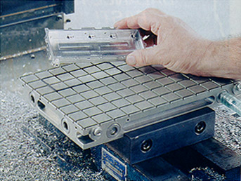
Vacuum workholding systems are recommended for many types of parts, including those that are thin and irregularly shaped, large and flat, and easily marred. Shown is a commercially available grid-type system. An elastic seal pressed into the plate’s slots conforms to the shape of the workpiece.
Others are aware of the benefits vacuum workholders offer, too. Manufacturers in the sheet metal, cabinet and computer-chip industries use vacuum chucks every day.
It’s doubtful, though, that many owners and managers of machine shops consider vacuum workholding systems a viable method for securing parts. They should. Vacuum chucks are good for machining the following:
Thin and irregularly shaped parts that are difficult to hold in a vise.
Workpieces made of aluminum and materials that mar easily.
Large, flat parts that would require too many clamps if held by conventional means.
Small parts that can be “nested” on one piece of material, allowing them to be machined in a single setup.
A vacuum chuck can generate hundreds of pounds of holding force, with the actual amount dependent upon the workpiece surface area exposed to the chuck. The maximum force that any vacuum-generating source can produce is 14.7 psi. So, under ideal conditions, the force holding a 10"x10" workpiece whose entire face contacts the chuck would be 1,470 lbs.
True, that holding force pales in comparison to what a mechanical chuck could supply. But if you regularly machine parts that are tough to secure by conventional methods, you might consider tapping into vacuum power.
Build Your Own
To build a vacuum workholding system, you’ll need a vacuum-generating source, like a vacuum pump, and a “chuck” to connect it to. The latter can be something as simple as a piece of particle board (Figure 1).
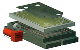
Figure 1: A typical vacuum chuck setup involving a large, flat part and a particle-board top plate. The vacuum generator draws air right through the porous particle board.
Many industrial routers have beds made of particle board. Inlets are located on the underside of the bed, which is porous enough to allow the pump to draw air through it.
Particle board works well for parts with large surface areas. It’s also cheap, so you can cut into it without worrying about replacement costs.
But there are two notable disadvantages to using this material in a machine shop. You will be forced to cut “dry,” as particle board is not resistant to cutting fluids. And it’s flammable. Machining causes friction, which creates heat. Enough heat, coupled with the considerable air flow through the particle board, can lead to fire. Obviously, you would never want to leave unattended any machining operation that involves a particle-board vacuum chuck.
Grid-type vacuum chucks are a better choice. You can buy one, although few companies produce them, or you can make your own out of a piece of aluminum tooling plate and an O-shaped rubber or neoprene cord.
Cut a checkerboard pattern of grooves into the plate. The grooves should be just wide enough to accept the cord and shallower than the cord is thick. (The cord should compress slightly under the weight of a workpiece.) Drill holes at the bottom of the grooves, part-way into the plate. Then, drilling from the edge of the plate, machine air passages that intersect with the holes. Another option is to hollow out the bottom of the plate and seal the cavity with a thin piece of aluminum and plumbers putty.
The checkerboard pattern allows you to arrange the cord to accommodate different workpieces. Also, holding force increases in direct proportion to the workpiece surface area exposed to the vacuum. So the more grooves that you machine into the plate, the greater your holding force will be.
A drawback of the general-purpose vacuum chuck like the one described above is that you shouldn’t machine through a workpiece while using it. If you do, you could either lose the suction that secures the part or ruin the chuck. One solution to the problem is a vacuum fixture (Figure 2).
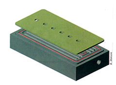
Figure 2: A vacuum fixture is configured for a specific part. Unlike some general-purpose vacuum chucks, you can machine through parts held by a vacuum fixture.
A vacuum fixture is custom-machined to exactly match the workpiece. Areas of the fixture that align with the through-machine areas of the workpiece are relieved and gasketed with cord. This permits you, for example, to drill through a workpiece instead of having to drill a partial hole that must be finished on another machine.
Suck It Down
There are many ways to create the suction that your workholding system will require, with vacuum pumps being the most common (Figure 3). Many different styles are available, and the price range is fairly broad.
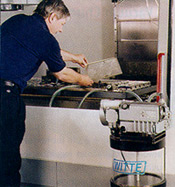
Figure 3: Vacuum pumps are available in many styles. Shown is a modular pump and a liquid separator.
Small industrial-grade pumps start at around $500. Larger pumps cost upwards of $5,000. For most shops, a smaller unit will suffice. A big pump is only necessary when a very large volume of air needs to be evacuated quickly or when the pump connects to multiple chucks.
For occasional use, consider a vacuum generator. It’s driven by compressed air that’s introduced via an air hose attached to one side of the unit. As the air moves through the generator, there is a Venturi effect, which creates the vacuum.
Vacuum generators are available for as little as $75, making them a cost-effective alternative to pumps. However, they also can be compressed-air-eating monsters, so vacuum generators tend to be used on a limited basis.
There is another consideration besides cost when deciding whether to purchase a vacuum pump or generator. A pump can be damaged if coolant or any other fluid enters it, an occurrence that you can prevent by properly plumbing the vacuum system. When liquid enters a vacuum generator, however, it sprays harmlessly out of the unit’s exit port.
A cautionary note before operating your vacuum chuck: Only use it on a fully enclosed machine. In case of a loss of vacuum, the cutting tool will inevitably grab the workpiece and begin whipping it around at a high rate of speed until either the tool or the workpiece disintegrates. The resulting shrapnel, obviously, could be very dangerous.
Why Use Vacuum Power?
At first glance, it may seem difficult to justify the use of vacuum workholders. You have to buy or build them, either of which requires an investment in equipment. You have to cut dry with them or guard against coolant entering your pump. And they don’t allow you to increase feeds and speeds. In fact, you may need to be less aggressive when using vacuum chucks, because their clamping forces aren’t as great as mechanical devices.
So why should you use vacuum workholders? Because they are the only way to hold certain types of parts—unless you want to break out that roll of double-back tape. Plus, for certain applications, they’re just more convenient to use than traditional workholders. Vacuum chucks allow you to do away with wrenches and vise handles. And if you need to machine thousands of parts, anything you can do to speed and simplify part handling makes sense.
For example, let’s say that you have a job that involves machining 5,000 widgets. When finished, the widgets are 2" square and 3/8" thick. Each takes 30 seconds to machine. You use three vises that each hold two parts. It takes you 30 seconds to change out six parts, resulting in a cycle time of 3 1/2 minutes. Completing the job with this workholding arrangement requires approximately 49 hours.
Now imagine cutting these same widgets from a sheet of 16"x32" material that’s 1/2" thick and secured with a vacuum chuck. Let’s assume that you can get 128 pieces from a sheet. At 30 seconds per part, this results in a cycle time of 64 minutes per sheet. If each sheet takes 30 seconds to load, the total time for the part run is roughly 42 hours—seven fewer than if you had used the vises.
At a shop rate of $75 per hour, you would save over $500 by using a vacuum chuck. Furthermore, assuming that it cost 15 cents apiece to saw the blanks that the vises held, you would save an additional $750.
You can see that, given the right application, a vacuum chuck will quickly pay for itself. And if you’re willing to try new ways to hold parts, vacuum workholders might offer the competitive edge you have been looking for.
About the Author
Kip Hanson is general manager at Allen Co., Edina, Minn.
Vacuum Chucks Save Time, Simplify Setups
Nature may abhor a vacuum, but apparently manufacturers don’t. A growing number of companies are using vacuum workholding systems because of their versatility and convenience.
One manufacturer of vacuum part-handling equipment, Anver Corp., Hudson, Mass., has seen a rise in the number of metalworking companies inquiring about vacuum chucks. The short amount of time it takes to set up a part on a vacuum chuck appeals to them, said the manager of Anver’s components group, Mark Laycox. “There isn’t as much setup time, because there aren’t any vises to set. You don’t have to mess around with clamp handles or torque wrenches.”
Several of IBAG’s Vac-Mat vacuum workholders secure a long airframe section.
Another advantage of vacuum chucks is that they can hold thin, flat parts without distorting, scratching or marring the parts. Some aircraft manufacturers use vacuum chucks to machine thin-walled instrument panels and window glass.
There are drawbacks to vacuum chucks, however. A big one is that some chucks won’t allow the operator to machine through a workpiece. Doing so will either break the vacuum seal that secures the piece or destroy the chuck.
A number of commercial products circumvent this problem. One is called Vac-Mat, a disposable plastic mat that’s offered by IBAG North America, North Haven, Conn.
The 0.098"-thick mat incorporates a series of workpiece “suckers,” each of which has a vacuum hole in it. Vac-Mat maintains vacuum pressure even when punctured because the suckers are independent of one another. This allows the operator to drill through-holes and mill pockets and cutouts.
Each mat costs $6.50. The entire Vac-Mate system runs about $5,000. IBAG recommends Vac-Mat for machining flat parts made of nonferrous metals, wood, plastic and composites.
— Derek Phillips
Router Bits Solve the Problem of Workpiece ‘Lift’
Cutting forces exerted by the spiral flutes of some tools have a tendency to lift up workpieces held by a vacuum chuck.
Drills and taps usually are not a problem, as these tools’ downward motion offsets any upward cutting force generated by their helixes. Endmills, however, are another story.
The lifting force generated by an endmill may be enough to yank a part off of a vacuum chuck. One solution to the problem is to use a router bit.
Router bits are available from suppliers of woodworking equipment and can be found on the Internet by entering “router bits” into your favorite search engine. A machinist venturing into a router bit Web site for the first time will be presented with new and sometimes bizarre terminology. Bits have names like Round-Over, Pilot, Fingernail and Roman Ogee.
The only page you need to bookmark, though, is the one labeled “Straight-Flute Router Bits.” They are the cutters of choice for most machining done with a vacuum chuck.
Straight-flute router bits only exert radial cutting forces, so they neither lift up nor push down on the workpiece. They are manufactured from either HSS or solid carbide, and some HSS models have carbide-tipped flutes. They are offered in single- and multi-flute configurations and cost about the same as conventional endmills.
Several manufacturers also offer CNC-ground bits. Specially designed for industrial applications, they are ground to tighter tolerances than standard products.
Router bits are not designed for cutting steel or other ferrous materials, but they perform admirably on aluminum, plastic and composite materials.
—K. Hanson
Related Glossary Terms
- chuck
chuck
Workholding device that affixes to a mill, lathe or drill-press spindle. It holds a tool or workpiece by one end, allowing it to be rotated. May also be fitted to the machine table to hold a workpiece. Two or more adjustable jaws actually hold the tool or part. May be actuated manually, pneumatically, hydraulically or electrically. See collet.
- composites
composites
Materials composed of different elements, with one element normally embedded in another, held together by a compatible binder.
- coolant
coolant
Fluid that reduces temperature buildup at the tool/workpiece interface during machining. Normally takes the form of a liquid such as soluble or chemical mixtures (semisynthetic, synthetic) but can be pressurized air or other gas. Because of water’s ability to absorb great quantities of heat, it is widely used as a coolant and vehicle for various cutting compounds, with the water-to-compound ratio varying with the machining task. See cutting fluid; semisynthetic cutting fluid; soluble-oil cutting fluid; synthetic cutting fluid.
- cutting force
cutting force
Engagement of a tool’s cutting edge with a workpiece generates a cutting force. Such a cutting force combines tangential, feed and radial forces, which can be measured by a dynamometer. Of the three cutting force components, tangential force is the greatest. Tangential force generates torque and accounts for more than 95 percent of the machining power. See dynamometer.
- endmill
endmill
Milling cutter held by its shank that cuts on its periphery and, if so configured, on its free end. Takes a variety of shapes (single- and double-end, roughing, ballnose and cup-end) and sizes (stub, medium, long and extra-long). Also comes with differing numbers of flutes.
- fixture
fixture
Device, often made in-house, that holds a specific workpiece. See jig; modular fixturing.
- flat ( screw flat)
flat ( screw flat)
Flat surface machined into the shank of a cutting tool for enhanced holding of the tool.
- flutes
flutes
Grooves and spaces in the body of a tool that permit chip removal from, and cutting-fluid application to, the point of cut.
- high-speed steels ( HSS)
high-speed steels ( HSS)
Available in two major types: tungsten high-speed steels (designated by letter T having tungsten as the principal alloying element) and molybdenum high-speed steels (designated by letter M having molybdenum as the principal alloying element). The type T high-speed steels containing cobalt have higher wear resistance and greater red (hot) hardness, withstanding cutting temperature up to 1,100º F (590º C). The type T steels are used to fabricate metalcutting tools (milling cutters, drills, reamers and taps), woodworking tools, various types of punches and dies, ball and roller bearings. The type M steels are used for cutting tools and various types of dies.
- metalworking
metalworking
Any manufacturing process in which metal is processed or machined such that the workpiece is given a new shape. Broadly defined, the term includes processes such as design and layout, heat-treating, material handling and inspection.
- milling machine ( mill)
milling machine ( mill)
Runs endmills and arbor-mounted milling cutters. Features include a head with a spindle that drives the cutters; a column, knee and table that provide motion in the three Cartesian axes; and a base that supports the components and houses the cutting-fluid pump and reservoir. The work is mounted on the table and fed into the rotating cutter or endmill to accomplish the milling steps; vertical milling machines also feed endmills into the work by means of a spindle-mounted quill. Models range from small manual machines to big bed-type and duplex mills. All take one of three basic forms: vertical, horizontal or convertible horizontal/vertical. Vertical machines may be knee-type (the table is mounted on a knee that can be elevated) or bed-type (the table is securely supported and only moves horizontally). In general, horizontal machines are bigger and more powerful, while vertical machines are lighter but more versatile and easier to set up and operate.
- sawing machine ( saw)
sawing machine ( saw)
Machine designed to use a serrated-tooth blade to cut metal or other material. Comes in a wide variety of styles but takes one of four basic forms: hacksaw (a simple, rugged machine that uses a reciprocating motion to part metal or other material); cold or circular saw (powers a circular blade that cuts structural materials); bandsaw (runs an endless band; the two basic types are cutoff and contour band machines, which cut intricate contours and shapes); and abrasive cutoff saw (similar in appearance to the cold saw, but uses an abrasive disc that rotates at high speeds rather than a blade with serrated teeth).
- tapping
tapping
Machining operation in which a tap, with teeth on its periphery, cuts internal threads in a predrilled hole having a smaller diameter than the tap diameter. Threads are formed by a combined rotary and axial-relative motion between tap and workpiece. See tap.
- web
web
On a rotating tool, the portion of the tool body that joins the lands. Web is thicker at the shank end, relative to the point end, providing maximum torsional strength.
Author

Kip Hanson is a contributing editor for Cutting Tool Engineering magazine. Contact him by phone at (520) 548-7328 or via e-mail at [email protected].