Do you ever need to drill small-diameter holes? Yes? How about really small holes, say, ones the size of a cricket’s leg? If you answered yes again, you understand the challenges involved in producing tiny holes.
Very small holes often require you to contend with tool breakage, the high cost and scarcity of drill bits, and insufficient spindle speeds.
One solution to these problems is to use circuit board drills. CB drills, as their name implies, produce holes in printed circuit boards. And since a lot of circuit boards are being manufactured these days, CB drills are readily available.
They typically are mounted in machine tools designed specifically for the production of circuit boards. These quick and highly accurate machines have multiple spindles that can run at speeds exceeding 100,000 rpm.
CB Drills’ Design a ‘Marvel’
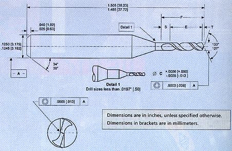
Inspecting a CB drill under a microscope reveals a marvel of modern manufacturing. It seems to be an impossibly small tool to incorporate polished flutes and a 4-facet point that is self-centering and free cutting.
CB drills have a standard 1/8"-dia. shank and an overall length of 1 1/2". They also have a higher length-to-diameter ratio than conventional drills. This is because when circuit boards are drilled, several units are stacked together. The cutting range for CB drills starts at 0.2500" and goes all the way down to 0.0039", which is roughly the diameter of a human hair.
Most CB drills are made of solid carbide. Less expensive ones, those with stainless steel shanks, are also available. The drills come with or without a plastic ring, which is attached to the shank 0.8000" from the tip of the drill and serves as a locating reference. By seating the ring against the face of the collet, the machinist can quickly and easily replace a broken drill without having to recalibrate the length.
CB drills’ low cost makes them an attractive choice for holes 1/4" in diameter and smaller. You can buy CB drills 1/16" to 3/16" in diameter for approximately 30 percent of the cost of conventional carbide drills. For a CB drill below 1/16" or above 3/16", expect to pay about 70 percent the price of a comparably sized carbide drill.
Although designed for drilling holes in composite circuit board material, CB drills should be considered for drilling other materials. They work well in aluminum, plastic and mild steels, as well as some of the softer 300- and 400-series stainless steels.
Producing holes in thin-wall tubing is one application where CB drills really shine. If you have a number of holes to drill in the 3/16"- to 1/4"-dia. range, it is possible to grind a cutting edge on the backside of the drill, where the drill body meets the shank. Since the shank of the drill is smaller than the drill body, this will allow you to drill through the tubing and then interpolate a chamfer on the backside of the hole.
The diameters of CB drills range from 0.2500" to 0.0039". For their size, they're surprisingly tough.
Operational Considerations
Like all drills, circuit board drills should be clamped in a clean, well-maintained collet chuck. Resist the temptation to clamp them in an endmill holder in order to take advantage of their 1/8" shanks. Endmill holders do not provide the accuracy that CB drills require. Due to the drills’ small size and the brittleness of carbide, their tips are sensitive to any misalignment. Even a miniscule amount of runout at the tip may cause a CB drill to deflect and break.
Always use an “on size” collet—one that’s been ground to precisely hold a 1/8" shank—rather than the more common metric collet. A 3.5mm ER16 collet has a clamping range of 0.1181" to 0.1378", which is adequate for holding a 1/8" drill shank. But collapsing the collet the required amount will probably result in more drill runout than is desirable.
If you intend to use a CB drill on a lathe, you will probably need to “dial-in” the tool with a dial indicator. This can be accomplished by attaching the indicator to the spindle and measuring the drill’s shank while rotating the spindle. It will then be easy to tweak the centerline of the tool accordingly with a small hammer or a precision adjusting instrument.
As mentioned earlier, the machines designed for drilling circuit boards have spindles that rotate at over 100,000 rpm. Unfortunately, few of today’s machining centers and lathes have spindles that exceed 10,000 rpm. Production drilling on a machining center may require you to retrofit your machine with a speeder head, a device with a miniature gear train that multiplies any rotational motion by a certain preset factor.
Another possibility is to make CB drilling a secondary operation. This can be done on a dedicated machine that offers higher spindle speeds than your machining center. And, if you are feeling inventive, high-speed air spindles, such as those used in small hand grinders, can be purchased at a reasonable price and jury-rigged into a toolholder.
You also have to consider your tool-changing system. Many modern machining centers are equipped with exchange-arm toolchangers. The high speed at which they swap out tools can snap off CB drills’ delicate tips. Some larger machining centers allow the operator to program an M code that decreases the tool-changing speed. This feature, designed for heavy tools, works equally well with CB drills.
Drilling and tapping machines change tools in an up-and-down motion. Although gentler on tools than an exchange-arm toolholder’s side-to-side motion, it’s a good idea to reduce the rapid-traverse speed when using CB drills. If all else fails, stop the program with an M00 command and change the tool manually.
As for speeds and feeds, normal rules simply do not apply to CB drills. Their small diameters demand a very high spindle speed in order for the tools to cut at a satisfactory rate.
The first thing to do is set aside everything you know about speeds and feeds and simply try making a few holes with a CB drill at whatever rpm your machine develops. You will quickly discover that the laws of physics seem different when working with a tool this small. CB drills are remarkably tough, given their size, and may surprise you by performing well at whatever speed you attempt.
You might want to start out at a feed of 0.0002 to 0.0005 ipr and gradually increase the rate until an acceptable production level is met or the drill breaks. After reaching one of these points, back off the feed rate slightly so you can achieve predictable tool life. At 10,000 rpm, a feed rate of 0.0005 ipr equals a material-removal rate of 5 ipm. That should be adequate for most jobs.
Unless you plan to apply a CB drill to an angled surface, center drilling or predrilling is unnecessary. In fact, the hole left by a center drill may actually force the CB drill to walk, which could cause it to break. The only requirement for starting a CB drill is a clean, flat surface. If you need to spot the workpiece, it is important to use a spotting drill with a web that is thinner than the CB drill’s. Finding such a tool could prove difficult, though, and may require you to purchase a custom-ground spotting drill, especially if you plan to drill very small holes.
A better alternative than spotting might be to begin drilling with the CB drill at a very low feed rate, to allow the drill to center itself, then gradually increase the feed as the drill stabilizes. This will mean programming the machine manually with a series of G00 and G01 commands, because a standard drilling cycle will not allow you to vary the feed rate during the cycle. It is also possible to write a parametric, or macro, program to alter the feed rate as the drill depth increases.
As with any holemaking operation, sometimes you’ll have to retract the CB drill to clear chips from the hole. Hole depth will determine how often you’ll be required to do this. You can usually drill several diameters deep without pecking.
Watch the chips closely. If they curl up and out of the hole, you probably won’t have to retract the drill. If you find that pecking is necessary, it is important to remove chips from the cutting area with a light air blast or spray mist. Removing the chips will help prevent them from being recut, which often leads to drill breakage.
Don’t Touch
One disadvantage of CB drills is their fragility. They are shipped in plastic containers that secure and protect them, and the smallest drills come with caps over their points. Use care when removing these caps and always replace them when finished, because any radial pressure applied to the drill point may cause it to break. Indeed, many of these tools are broken simply because inquisitive fingers want to touch their points.
It’s also fairly easy to force a CB drill deep into your finger, where it inevitably breaks off. On a positive note, however, a CB drill is great for drilling a tiny pressure-relief hole in a big toe that has had a piece of bar stock dropped on it. (Ouch!)
Although CB drills are fragile and often require careful handling, these frequently overlooked tools should be a part of any machine shop’s arsenal. Their standard shanks help reduce the need to stock multiple collet sizes. Their carbide construction makes them surprisingly tough, and, compared to conventional carbide drills, they’re inexpensive.
Spend a few dollars and test one out. You just might realize big benefits.
About the Author
Kip Hanson is general manager at Allen Co., located in Edina, Minn.
Related Glossary Terms
- center drill
center drill
Drill used to make mounting holes for workpiece to be held between centers. Also used to predrill holes for subsequent drilling operations. See centers.
- center drilling
center drilling
Drilling tapered holes for mounting workpiece between centers. Center-drilled holes also serve as starter holes for drilling larger holes in the same location. See centers; drilling.
- centers
centers
Cone-shaped pins that support a workpiece by one or two ends during machining. The centers fit into holes drilled in the workpiece ends. Centers that turn with the workpiece are called “live” centers; those that do not are called “dead” centers.
- chuck
chuck
Workholding device that affixes to a mill, lathe or drill-press spindle. It holds a tool or workpiece by one end, allowing it to be rotated. May also be fitted to the machine table to hold a workpiece. Two or more adjustable jaws actually hold the tool or part. May be actuated manually, pneumatically, hydraulically or electrically. See collet.
- collet
collet
Flexible-sided device that secures a tool or workpiece. Similar in function to a chuck, but can accommodate only a narrow size range. Typically provides greater gripping force and precision than a chuck. See chuck.
- endmill
endmill
Milling cutter held by its shank that cuts on its periphery and, if so configured, on its free end. Takes a variety of shapes (single- and double-end, roughing, ballnose and cup-end) and sizes (stub, medium, long and extra-long). Also comes with differing numbers of flutes.
- feed
feed
Rate of change of position of the tool as a whole, relative to the workpiece while cutting.
- flat ( screw flat)
flat ( screw flat)
Flat surface machined into the shank of a cutting tool for enhanced holding of the tool.
- flutes
flutes
Grooves and spaces in the body of a tool that permit chip removal from, and cutting-fluid application to, the point of cut.
- inches per minute ( ipm)
inches per minute ( ipm)
Value that refers to how far the workpiece or cutter advances linearly in 1 minute, defined as: ipm = ipt 5 number of effective teeth 5 rpm. Also known as the table feed or machine feed.
- lathe
lathe
Turning machine capable of sawing, milling, grinding, gear-cutting, drilling, reaming, boring, threading, facing, chamfering, grooving, knurling, spinning, parting, necking, taper-cutting, and cam- and eccentric-cutting, as well as step- and straight-turning. Comes in a variety of forms, ranging from manual to semiautomatic to fully automatic, with major types being engine lathes, turning and contouring lathes, turret lathes and numerical-control lathes. The engine lathe consists of a headstock and spindle, tailstock, bed, carriage (complete with apron) and cross slides. Features include gear- (speed) and feed-selector levers, toolpost, compound rest, lead screw and reversing lead screw, threading dial and rapid-traverse lever. Special lathe types include through-the-spindle, camshaft and crankshaft, brake drum and rotor, spinning and gun-barrel machines. Toolroom and bench lathes are used for precision work; the former for tool-and-die work and similar tasks, the latter for small workpieces (instruments, watches), normally without a power feed. Models are typically designated according to their “swing,” or the largest-diameter workpiece that can be rotated; bed length, or the distance between centers; and horsepower generated. See turning machine.
- machining center
machining center
CNC machine tool capable of drilling, reaming, tapping, milling and boring. Normally comes with an automatic toolchanger. See automatic toolchanger.
- shank
shank
Main body of a tool; the portion of a drill or similar end-held tool that fits into a collet, chuck or similar mounting device.
- stainless steels
stainless steels
Stainless steels possess high strength, heat resistance, excellent workability and erosion resistance. Four general classes have been developed to cover a range of mechanical and physical properties for particular applications. The four classes are: the austenitic types of the chromium-nickel-manganese 200 series and the chromium-nickel 300 series; the martensitic types of the chromium, hardenable 400 series; the chromium, nonhardenable 400-series ferritic types; and the precipitation-hardening type of chromium-nickel alloys with additional elements that are hardenable by solution treating and aging.
- tapping
tapping
Machining operation in which a tap, with teeth on its periphery, cuts internal threads in a predrilled hole having a smaller diameter than the tap diameter. Threads are formed by a combined rotary and axial-relative motion between tap and workpiece. See tap.
- toolholder
toolholder
Secures a cutting tool during a machining operation. Basic types include block, cartridge, chuck, collet, fixed, modular, quick-change and rotating.
- web
web
On a rotating tool, the portion of the tool body that joins the lands. Web is thicker at the shank end, relative to the point end, providing maximum torsional strength.
Author

Kip Hanson is a contributing editor for Cutting Tool Engineering magazine. Contact him by phone at (520) 548-7328 or via e-mail at [email protected].