The Performance Edge: Drilling Performance
This article makes the case that a core drill is the best tool for opening existing holes.
A core drill’s two cutting edges give it an advantage over the single-point tools that machinists typically use to open existing holes.
Until recently, machinists couldn’t use the right tool to open an existing hole, because no such tool existed. The tools they used were adequate for cutting into the walls of holes that had been cast, punched, or drilled into the workpiece, but they weren’t ideal. They didn’t have the stability to cut deeper holes or the convenience of an indexable-insert design. It wasn’t until the introduction of the 2-flute indexable core drill that machinists had a tool specifically designed for the job.
Parts with existing through or blind holes frequently need machining to straighten the holes, improve their circularity and cylindricity, smooth their inner walls, and enlarge their diameters to a specified dimension. Over the years, machinists have tried using brazed single-point turning tools, indexable drills, and single-point boring bars to perform these tasks. Many have switched to indexable-insert core drills because the new tools cut more accurately and are easier and less expensive to maintain. These machinists are using core drills in rotating applications on milling machines and machining centers and nonrotating applications on lathes.
Specialized Design
Although core-drill designs vary from manufacturer to manufacturer, all are based on the design of a double-sided or 2-flute indexable-insert boring bar. Traditionally, core drilling was considered a roughing operation, but 2-flute indexable-insert core drills are capable of finishing an existing hole as well. Specially designed core drills incorporate a chamfering insert, which allows the machinist to open the hole, finish it to size, and chamfer it with one tool.
Most core drills use WCMT-style inserts. These inserts are stronger than other styles because of their trigonal geometry and chipgroove configuration. The unevenness of many existing holes makes a strong insert necessary. The sudden changes in depth of cut (DOC), caused by variances in the hole’s diameter, can break a weak insert (Figure 1). The added strength also helps the core-drilling insert withstand the impact of an interruption in the wall of the hole.
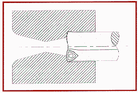 |
Figure 1: The varying diameter of this cast hole causes the DOC to change as the core drill machines the length of the hole. |
The specific insert grade needed to core drill depends on the material to be cut, the DOC chosen, and the required finish. Generally, machinists can use the same insert grade for core drilling that they would use for turning the same material at the same speed and feed.
Table 1 lists the insert grades, speeds, and feeds that can be used to cut common ferrous materials. Nonferrous materials can be core drilled as well. Chemical-vapor-deposition (CVD)-coated carbides are available for general applications and operations that require toughness and wear resistance. Physical-vapor-deposition (PVD)-coated carbides are available for low-speed applications and operations that require toughness. PVD-coated carbides also are ideal for stainless-steel applications. More machinists are turning to cermet inserts for stainless steel because of the grade’s finishing capabilities and the ability to machine with cermets at higher speeds. Uncoated cermets are available to core drill a wide variety of materials in operations ranging from semi-roughing to finishing. New coated cermets are available for the semi-roughing to finishing of carbon steels, alloy steels, tool steels, and stainless steels. PVD-coated cermets combine the wear resistance of a cermet with the toughness of a carbide.
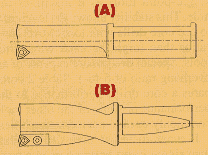
Figure 2: Core drills are offered with either a fixed-pocket (A) or cartridge (B) design.
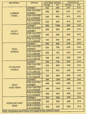
Table 1: Machining recommendations for core drilling various materials. Speeds are given in sfm, feeds in ipr.
In some core drills, the insert fits into a fixed pocket. Others incorporate a cartridge-style pocket that allows the tool to be shimmed out in either the x- or z-axis (Figure 2). In addition to their adjustability, cartridge-style tools are easily repaired. Damaged pockets can be fixed by simply replacing the cartridge.
Twice the Performance
By doubling the number of effective cutting edges, the 2-flute core drill is able to open existing holes more efficiently than the single-point tools traditionally used for this operation. The cutting forces on a core drill’s two opposing inserts are balanced, being equal and in opposite directions. As a result, the core drill is more stable than single-point tools as it machines the hole. This stability allows the machinist to use core drills with longer overhang ratios than might be used with other tools. Special designs are capable of an overhang ratio of 5-to-1. Table 2 compares a core drill’s performance to the performance of some of the other tools commonly used to open existing holes.
If machinists use core drills rather than single-insert boring bars in a turning operation, they will be able to cut at a feed rate up to two times higher. The DOC can be greater as well. Machinists accustomed to using brazed tools, spade drills, or solid drills to open existing holes with lathes, milling machines, or machining centers, also will be able to remove metal faster with core drills. These machinists will spend less on tool maintenance and inventory as well. A dull core drill can be restored to usable condition simply by indexing or replacing its inserts. Only the inserts need to be stocked in significant numbers. The diversity of insert grades available makes it possible to use the same cutter body to core drill a wide variety of materials.
Using either a single-insert boring bar or a brazed single-point tool, a machinist might have to machine an existing hole in several passes to achieve the desired geometry. With a 2-flute core drill, a machinist can rough and even finish the hole in one or two passes (Figure 3).
In a milling-machine or machining-center operation, a core drill can replace the single- or multiflute endmills machinists typically use to machine an existing hole to a larger diameter. Being designed specifically for opening existing holes, a core drill has the lead and rake angles and overall configuration necessary to maintain balanced cutting forces while machining the walls of a hole. The core drill can cut at a higher feed rate than a single-flute endmill can cut, because the balanced forces on the core drill’s cutters prevent chatter and deflection. When used in a plunge-milling operation, the core drill can even work as an endmill.
|
Lathe Operations |
||
| Operation | Used Tools | Core Drill’s Advantages |
| Machining an existing drilled or punched hole to a larger diameter | Single-flute boring bar | 2-insert design creates balanced cutting forces |
| Brazed tools, Spade drills, Solid drills |
Higher speeds
Indexable inserts make it possible to restore sharpness quickly and inexpensively Wide variety of inserts available broaden the tool’s applicability. |
|
| Indexable drills | Higher feed rates
Balanced cutting When using cartridge style, design protects the cutter body and makes small adjustments possible |
|
| Machining a cast hole to a larger diameter | Boring bars Brazed tools Spade drills indexable drills |
Same advantages as those listed above
Holes can be straightened in one pass Cutting forces remain balanced even when cutting parts with core shifts |
|
Milling-Machine/Machining-Center Operations |
||
| Machining an existing drilled, punched, or cast hole to a larger diameter | Single-and multiflute endmills | Balanced cutting forces
Higher feed rates than those used with single-flute tools When using cartridge style, design protects the cutter body and makes small adjustments possible. |
| Brazed tools Spade drills Solid drills |
Higher speeds When using cartridge style, design protects the cutter body and makes small adjustments possible |
|
| Indexable drills | Higher feed rates Balanced cutting When using cartridge style, design protects the cutter body and makes small adjustments possible |
|
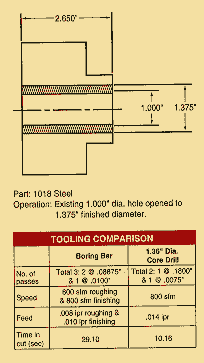 |
Figure 3: In a typical core-drilling operation such as this, a core drill can open a hole 65% faster than a boring bar. |
Because of its balanced cutting forces, the core drill can open holes produced in a variety of ways. Not only can it open drilled holes, which tend to be the straightest and smoothest of the existing holes, but also punched holes, which are more likely to be off-center and have rough sides. A core drill can even open a cast hole in one pass. This is the most challenging type of existing hole to work with. Cast holes may have scale that must be removed from their walls, and they may be irregular in size and shape. A tool used to correct these imperfections will probably encounter varying DOCs and material of varying hardness. The stability of the core drill allows it to cut such holes to the proper dimensions even if the hole was formed with core shifts.
It may seem as if a 2-flute indexable drill would offer many of the same advantages as a core drill. But indexable drills are not recommended for opening existing holes. An indexable drill will cut the perimeter of an existing hole with only one of its cutting edges. The other insert is set to cut in the center when the drill is making a hole in solid material. With only one effective cutting edge in an existing hole, the indexable drill experiences unbalanced forces that make it impossible to open the hole effectively.
Core-Drilling Tips
DOCs as great as 0.30″ per side can be used with indexable-insert core drills. The DOC for a typical roughing cut with a core drill is 0.15″ per side, and a typical finishing cut is 0.01″ to 0.02″.
Whether a core drill is used in a stationary or rotating operation, both the machine and the work fixturing should be as rigid as possible to prevent vibration and chatter. Typically, core drilling takes more horsepower than boring with a tool of the same diameter, because a core drill cuts twice as deep as a boring tool, and it is fed into the workpiece twice as fast. The precise amount of horsepower needed will depend on the core drill’s diameter, but even the smallest core drill will require at least 5 hp.
The machine tool should be able to deliver a generous and uninterrupted supply of coolant to the cutting edge. Coolant delivered through the tool is recommended, but flood coolant works well in most applications. In addition to carrying heat away from the cutting edge, coolant must be used to control chips. The greater DOCs used with core drilling produce larger chips, which can quickly fill the hole and collide with the cutting edge. To evacuate the chips and deliver the most coolant to the cutting edge, the machinist should set the machine for the highest possible coolant pressure and volume.
The same core-drill body can be used to open holes of different diameters. By shimming out the tool’s inserts, a machinist can core drill a hole that is wider than the tool. The core drill also can be offset from the hole’s centerline to cut a wider hole with just one cutter. This allows a machinist to use both cutters and a heavy DOC to open a hole with a roughing pass in one direction and then offset the tool before it is withdrawn from the hole to back bore a finishing pass on the tool’s way out. In some cases, this two-way cutting can eliminate any secondary operations that may have been required using conventional tools.
To open an existing hole, a machinist can choose from a number of tools. But only core drills are designed to withstand the forces and conditions that are unique to the task. These designs allow machinists to open existing holes more efficiently and at less cost.
About the Author
Brent Lindsey is an applications engineer with the Ceratip Technical Center, Kyocera Industrial Ceramics Corp., Mountain Home, NC.Glossary terms in this article

MFGAxis Discussion