Optimizing Deep-Hole Drilling
Drilling with a single- or double-tube system might be the most efficient way to drill deep holes in some applications.
If you perform any type of deep-hole-drilling operation, you already know what a bottleneck the process can be. Even using a gundrill, you must strike a compromise between productivity and quality to produce a hole with a depth-to-diameter ratio of greater than 5-to-1. The good news is that there is a way to drill deep holes without compromising productivity or quality. With an upgrade to a single- or double-tube drilling system, you can pull out all the stops. The switch can provide at least five times higher productivity than conventional twist, spade, or gundrilling methods (Figure 1). And even at these levels of productivity, the holes will be accurate, straight, and well within tolerances.
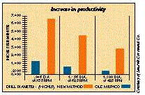
Figure 1: These graphs show one shopšs results after converting its gundrilling operation to a single-tube drilling system. As the graphs reveal, the shop saw a 5-to-1 improvement in throughput across all three diameters it was drilling.
Most shop owners and managers may be wondering at this point if they can afford such a system. The simple answer is yes, they can. Although the cost of converting a machine tool to use a single- or double-tube system can be $20,000, the conversion cost can be recouped in a short period of time through higher productivity. Based on the experience of shops that have already converted to this type of deep-hole drilling, the average shop can expect a return on its investment in six months. And, according to these same statistics, a shop that makes the switch should enjoy ongoing economies of about $75,000 per year. Such economic benefits make it more cost-effective for a shop to convert existing machines rather than buying new machines or adding another shift.
In some cases, a shop may gain even more by changing to a single- or double-tube system. For example, one military contractor saved $18 per part by converting its lathe to a double-tube system. Prior to the conversion, it was using gundrills to produce a weight-reduction hole in a 4140-steel axle. The switch to a double-tube drilling system cost the company $20,000, but it realized a return on the tooling investment in 21 days.
Access Denied
For a drilling system to produce deep holes with both speed and precision it must overcome the inherent problems and limitations of the deep-hole-drilling process. Generally, a hole is defined as a deep hole when the depth-to-diameter, or aspect, ratio is more than 5-to-1. To drill a hole this deep, a shop must use a machine with at least 10 hp for every 1″ of drill diameter; a drill with a strong, sharp chipbreaker; and a lot of cutting fluid.
Chip disposal is the main problem users of deep-hole-drilling systems must contend with. The deeper you drill, the farther the chip must travel from the toolšs cutting edge to the top of the hole. The greater the distance, the greater the chance the chip will jam or bind in the drill flute on the way out.
The difficulty of delivering cutting fluid to the drilling face at the bottom of a narrow hole further complicates the deep-hole-drilling process. If too little coolant makes its way to the drillhead, the risk of metal building up on the cutting edges increases. This built-up edge (BUE) hinders the toolšs ability to break chips. Another function of the coolant is to fight friction between the drill, chip, and hole wall. If friction is allowed to build because of a lack of coolant, the resulting torsional forces can snap the drill.
But BUE and coolant starvation arenšt the only problems plaguing deep-hole-drilling operations. The basic principle in deep-hole drilling is to press the toolšs carbide cutting edges into the work at high feed rates. This type of machining generates high cutting forces, and it takes a rigid tool to avoid deflection in the presence of these forces. Also, the adverse conditions typically found in a deep hole make it difficult for an operator to maintain straightness, roundness, diameter, and finish. If the drill begins to produce a hole with flawed geometry or finish, the problem usually becomes compounded the deeper the drill cuts.
The Inner Path
Single- and double-tube drilling systems avoid the problems associated with deep-hole drilling by routing coolant and chips through a hollow shaft inside the drill. The amount of pressure needed to force the coolant to the bottom of the hole and back out through the drill shaft ranges from 200 to 500 psi, depending on the system configuration and the diameter of the drill. A single-tube drill is a hollow tube with a drillhead attached to the end. With single-tube drilling, incoming fluid is pumped under pressure to the cutting face through the annular space between the outside of the tube and the wall of the hole itself. The width of this space typically measures about 0.040″, but it varies with the drillšs diameter. After the cutting fluid travels to the bottom of the hole to cool and lubricate the cutting edge and flush out the chips, it exits through the tubular drill shank, carrying the chips along with it (Figure 2a).
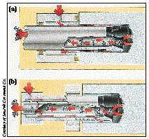
Figure 2: With a single-tube drilling system, cutting fluid is pumped between the drill and the hole wall and it exits with chips through the inside of the drill tube (a). With a double-tube system, the cutting fluid is pumped through the inlet in the connector and flows between the drill tube and the inner tube to the drillhead (b).
For hole diameters from 0.50″ to 0.75″, a single-tube drilling system is the only tubular system that can be used. Hole diameters larger than 0.75″ provide enough clearance for a double- or a single-tube system. A double-tube system consists of a drillhead, drill tube, inner tube, connector, collet, and sealing sleeve. The drillhead itself has an arrangement of two, three, or more cemented-carbide cutting edges, depending on the diameter of the drill. Some drillheads are fitted with several brazed tips, positioned so that they overlap. Other heads have pockets for disposable indexable inserts. Chipbreakers are individually ground or form-sintered in each tip to provide uniform chipbreaker width. Because cutting forces are not balanced in deep-hole drilling, double-tube drills have two strategically located support pads. These pads ride on the hole wall to keep the drill centered and allow the operator to run the tool at accelerated speeds.
A double-tube drilling system routes the cutting fluid down through the space between the outer and inner tubes. Most of this fluid is forced at a high pressure and flow rate through the holes in the drillhead to cool and lubricate the support pads and cutting edges. The fluid that doesnšt exit at the drillhead flows back up the middle of the inner tube. As the fluid rushes up the tube, it creates an aspirator-type vacuum, or ejector effect, to facilitate chip evacuation and return-coolant flow (Figure 2b).
The full-circle cross sections of single- and double-tube systems make them inherently more rigid than gundrill systems. A gundrill system removes chips through a V-shaped groove in the drill shank. To provide enough clearance, the width of this groove must equal three-fourths of the drillšs diameter. Removing this much of the drillšs shank for chip clearance seriously compromises the drillšs rigidity. A single-tube system does not require a groove in its shank, because chip evacuation is internal. This leaves the toolšs cross section completely round, which is a much more rigid shape than the gundrillšs cross section.
A double-tube system is even more rigid than a single-tube system of the same length, because very little clearance is required between the drill hole and the double-tube drillšs outer tube. A single-tube drill must allow additional clearance for the passage of coolant. The double-tube drillšs reduced need for clearance allows larger diameter drills to be used, and with the larger diameter comes greater rigidity. As a result, the risks of vibration, hole damage, and the loss of the holešs centerline are minimal.
With all of these advantages, single- and double-tube systems can drill holes in most work at 250 sfm. High-temperature alloys can be drilled at 100 to 150 sfm. Feed rates average 0.010 to 0.015 ipr for most work and drop to 0.006 to 0.008 ipr for high-temperature alloys. The systems can achieve tolerances of ą0.003″ and straightness of ą0.002 to 0.004 in./ft. regardless of hole depth.
Operational Requirements
The experience of hundreds of users has shown that single- and double-tube drilling systems can rapidly pay for themselves through significant improvements in productivity and quality. To achieve these levels of performance, however, users must be prepared to meet certain preconditions, make sure their shop floors are adequately equipped, and select the appropriate system for their needs. In addition to a machine with ample horsepower and rigidity, a user will need a sizable cutting-fluid reservoir able to deliver adequate pressure and volume. Larger holes require a greater amount of fluid, but at a lower pressure.
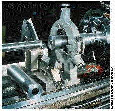
Single-tube systems can be installed only in dedicated high-power deep-hole-drilling machines. A double-tube system can be adapted relatively easily for use on a horizontal lathe, machining center, or boring mill, provided the machine has adequate power (Figure 3). To use a double-tube system on a nondedicated machine, such as a machining center, a shop should consider installing a modular quick-change toolholder as well. This will enable the operator to perform a 20- to 30-second tool swapout between jobs. When using a double-tube system on a machining center, the operator typically relies on a predrilled pilot hole for guidance rather than the drill bushing. On a lathe, the bushing provides guidance.
Single-tube systems require a seal between the drill bushing and the top of the hole to prevent cutting fluid from escaping through this space. In double-tube systems, however, no seal is required, because the fluid passing between the inner and outer tube has no chance to escape. Therefore, a double-tube system would be the better choice for machining operations where sealing problems are a concern.
Disposable drillheads eliminate the time and costs associated with regrinding. Therefore, in most cases it is advantageous to use them instead of regrindable drillheads. The ability to quickly replace worn edges significantly enhances productivity. One manufacturer, for instance, reduced edge-changing time from 15 minutes to two minutes by switching from a gundrill to an indexable single-tube system. To index, the operator simply twists off the head and replaces the bit. No edge measurement or offsetting is necessary. Another option is drillheads with indexable inserts. They are used for generating hole diameters larger than 2.5″ and are available for both single- and double-tube systems. Indexable-insert drillheads reduce machining costs by providing more edges per insert and allowing operators to replace worn inserts as well as support pads. Trepanning and counterboring heads also are available for varying hole diameters.
Deep-hole-drilling machines often allow the operator to choose to drill by rotating the workpiece, rotating the tool, or rotating both. Typically, the operator rotates the workpiece and leaves the drill stationary. However, if the operator is drilling asymmetrical workpieces and the holes are not too deep, he will produce better holes by rotating the tool and leaving the workpiece stationary. This method must be used with some caution, however, because the higher risk of deflection causes hole straightness to suffer as the holešs aspect ratio increases. To achieve the straightest holes with the best surface finish, ovality, and tolerances in the deeper holes, the operator should rotate the part or rotate both the drill and workpiece in opposite directions.
Breaking Chips Efficiently
In deep-hole drilling, chip evacuation is even more important than in conventional drilling. Excessively long, large chips should be avoided to prevent frequent tool maintenance. The solution is to generate chips that are of the right size. An optimal chip is as long as it is wide. However, the operator should not overload the cutting edge during chip formation to control machine power and heat buildup. Rather, he should increase the feed and/or reduce the cutting speed or use a shorter or wider chipbreaker to generate a chip of optimal size.
Single-tube drilling is the only tubular drilling system that can be used on smaller diameter holes ranging from 0.50″ upward. A single-tube system also removes chips more efficiently than a double-tube system when it comes to deep holes in longer workpieces. If the holešs depth-to-diameter ratio is up to 100-to-1, a single-tube system is the appropriate system to use. For ratios up to 50-to-1, a single- or double-tube system will work equally well.
The single-tube system also works better in tougher, difficult-to-machine materials such as exotics (e.g., Inconel), stainless steels, and low-carbon steels. For example, a manufacturer of oil-well production-tubing accessories is using a single-tube system to drill deep holes in Monel, Inconel, and Hastelloy. For these operations, the company has found it can produce the holes, on average, five to 15 times faster than it could using conventional gundrilling.
Shops might consider using a double-tube system on holes that would not be considered deep holes because their depth-to-diameter ratios are less than 5-to-1. Even on these holes, the double-tube system will provide 80% higher productivity than what could be achieved with spade or twist drills. The surface finish will be better as well. With a conventional spade or twist drill, surface finish is usually not better than 400 rms; a double-tube system can produce a surface finish of 60 rms on average.
If youšre not satisfied with your present deep-hole-drilling results, or if youšre in the process of upgrading or replacing older equipment anyway, it’s worth taking a fresh look at newer drilling tools. Your justification for considering a change is 80% higher metal-removal rates and an ROI of approximately six months.
About the Author
Christer Larsson is product specialist, drilling tools, for Sandvik Coromant Co., Fair Lawn, NJ.


MFGAxis Discussion