The Need for Feed Units
The Need for Feed Units
There are several types of feed units for drilling and tapping on the market, varying in capability and the type of drive. This article discusses the difference between units and suggests questions users should ask themselves before selecting a unit. Factors to be considered include the volume of production, cost engineering and tool requirements.
Feed units come in a bewildering array of shapes and sizes. Choosing the right one for your needs requires some homework, but it can dramatically improve your bottom line.
A feed unit is more than just an automatic drill press. It is an automated, self-contained, modular machining unit usually offering two axes of motion - spindle rotation and linear feed. It can do everything from drilling and tapping to drill/reaming, reaming, and thread rolling. The feed mechanism, which usually extends the spindle in a quill, can be driven mechanically, hydraulically, or pneumatically. A feed unit typically can perform both rapid advance and controlled feed and provides position feedback through limit sensors or encoder/resolver feedback for integration into machine control.
If properly selected and applied, feed units can offer a rich payoff. However, customers who are unaware of all the variables involved when purchasing a feed unit may end up with a poor feed unit application or setup, a slow production rate, and frustrated machinists.
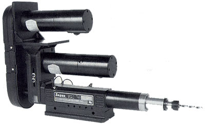
Figure 1: AN MQ-150 ball-screw feed unit from Zagar Inc.
Mechanical, hydraulic, and pneumatic feed units each have different features and functions that perform best when used for certain applications. For instance, when drilling with a carbide tool, a mechanically driven ballscrew feed unit extends tool life and enhances hole quality, because its constant feed rate translates into constant chipload on the tool. This constant chipload is crucial for the well-being of carbide tools, which are more brittle than their HSS counterparts and therefore less tolerant of uncontrolled feed-rate variation. In contrast, a pneumatic or hydraulic piston-type unit provides a constant-force feed, which may suit the requirements of a particular tool such as a deburring bit or a flow drill. A flow drill requires a constant force to melt the material it is cutting. The quill advances at a rate controlled by material removal.
These differences are vital in the selection of a feed unit. After dissecting the types of units further, you can be sure you are selecting the right unit for your applications. When purchasing a unit for a retrofit application, you almost always have to consider the existing tools and select a unit accordingly, whereas a new-unit purchase may or may not be beholden to a certain tool. The question then is whether to select the tool first or the feed unit first. The selection of the first item constrains your choices for the second. With the flexibility of some of today's programmable ballscrew feed units, this problem can be avoided. Such units can be programmed to simulate any requirements, including even the constant-force operation of a piston-type unit.
Mechanical Feed Units
When contemplating a mechanical feed unit, the major types to consider are ballscrew feed, cam feed, gear-driven, and leadscrew.
Ballscrew units are on the high-tech edge of feed-unit capability, offering flexibility, programmable controls, high power, and precision. In the ballscrew unit (Figure 1), the ballscrew provides the feed through some form of transmission from the feed motor (usually a servomotor) such as a coupling, belt and pulleys, or gears. Some units have the quill attached directly to the ballscrew nut, while others have the ballscrew nut attached to the quill by a connection device. In the latter type, the ballscrew is offset from the centerline access of the spindle and quill. A direct coupling to the ballscrew nut provides high-efficiency thrust on the tool's centerline axis. This also results in minimized deflection, a major consideration in precision tooling.
In the cam feed unit (Figure 2), a cam follower, attached to the quill, follows the path of either a rotary drum cam or a linear (kidney-shaped) cam. As the cam rotates slowly through some means of speed reduction (via a gear box or a harmonic drive), it advances the quill in relation to the path that is cut into the cam. The harmonic-drive type of speed reducer is a high-ratio, mechanical device. The speed reducer turning the cam, with reductions up to 200:1, is often turned by the same motor used to rotate the spindle. This is achieved with either a secondary belt and pulley or a gear transmission connecting the speed reducer and the spindle. This results in synchronization of the spindle speed and quill feed. To achieve this type of speed reduction, a harmonic-drive speed reducer is often used. Varying combinations of belts and pulleys connecting the spindle to the speed reducer adjust for speed and feed requirements.
The cam feed unit is the least flexible of mechanical feed units. The cam has a permanently machined path cut into it for the drilling cycle, including rapid advance, feed, and retract sections. The only way to adjust the cycle is to install a new cam. The cam is a custom part, made from a standard blank, and is more expensive than a stock part. Its replacement time can be extensive, depending on how deep inside the unit it is located. To many high-production lines, however, the cam feed unit is attractive for its rock-solid consistency in part-feature repeatability. The cycle parameters simply cannot be modified.
Gear units employ a gear drive for transmission from source to output. There are many types of gear units, and the gear drive can be used for the spindle and/or the quill feed.
The largest percentage of gear units are configured as tapping units, because the gearing lends itself so well to synchronized rotation and feed. The gear transmission can be a rack-and-pinion assembly, a gear-reduction drive synchronized with the spindle rotation, or a gear transmission driving a leadscrew. The tap pitch is altered by changing the two drive gears' ratio or, with a leadscrew unit, by changing the leadscrew and leadscrew-nut pitch.
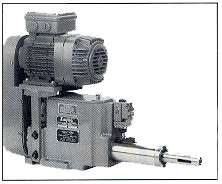
Figure 2: A CFQ-2 cam feed unit from Zugar Inc.
Leadscrew tapping units advance the tap at the pitch of the leadscrew. These units fall under the category of "some assembly required." When you want to change the tap pitch, you have to change the leadscrew and the leadscrew nut. Machine operators should be able to access this part of the unit and perform the changeover. The time needed to change the leadscrew (5 to 20 minutes) must be factored into the production requirements for this type of unit. (If this downtime is deemed unacceptable, a programmable ballscrew unit may be a good alternative, because it allows quick entry of pitch, part number, and tap size, for example, depending on how it is programmed.)
Low-speed operations usually require gear reduction of the motor. The most common type of motor used for these units is a reversing brake motor, which provides almost instant deceleration and reversal for tap retraction.
Drilling can be performed with these units only if the leadscrew is removed.
Pneumatic Feed Units
Both the spindle and the quill can be air-powered in pneumatic feed units, currently the most popular feed-unit type. This popularity is enhanced by the fact that the power and installation needs of these general-purpose, lower-cost units are familiar to most production personnel. Most feed-unit manufacturers offer this type of unit. Low-power, compact varieties of pneumatic feed units employ an air motor to power the spindle. These units often are used in light-duty applications such as drilling aluminum.
On most pneumatic feeds, a piston-style quill advances and retracts the spindle via air power. Other units employ a spring-loaded return rather than an air-powered return.
A pneumatic feed unit without an air motor employs an electric motor to power the spindle, the most common variety being a fixed-speed AC motor using pulley combinations to vary speed. Variable-speed DC motors and AC motors with an inverter for speed variation also are popular. The feed rate is most often controlled with an additional hydraulic feed-control cylinder, adjusted manually from outside the unit (Figure 3). The units move forward in rapid advance until they engage the feed-control cylinder and enter into the feed for the length of stroke of the hydraulic cylinder or until they hit a positive-stop mechanism on the unit.
For all pneumatic units, the adjustment of depth control for blind holes is controlled by adjusting the positive stop. Depending on the pneumatic-control system and limit sensors used, these units may be capable of stopping in midstroke.
Hydraulic Feed Units
The hydraulic unit is similar to a pneumatic unit, but it uses hydraulic fluid for power transmission. A hydraulic unit can reach much higher thrust levels than a like-size pneumatic unit. An electric motor usually is employed. A hydraulic motor, used on some units, delivers a lot of power for its compact size. If a large number of hydraulic units using hydraulic motors are installed on one machine, large hydraulic tanks may be needed to meet flow requirements.
Both rapid advance and feed are powered hydraulically. Because the feed can be controlled by the same system as the rapid advance, the external hydraulic control cylinder is eliminated.
Parameters
Once you've gathered information about the various types of feed units available, examine your company's general, engineering, and tooling requirements for using feed units.
General Requirements. Identify your company's performance/production, cost, and unit life-cycle requirements. Performance and production requirements vary dramatically from one user to another. Some shops purchase low-cost, less rugged feed units and treat them as short-life, disposable equipment. But for shops that require units with more power for longer-run production, this is not a practical strategy. Today's feed units have been designed for these extended-use applications. They are more reliable and can achieve longer maintenance cycles than ever before.
In determining your needs, ask yourself: Is my machine operating 24 hours a day, five to seven days a week? Or is the machine only operating two to three hours a day, two to three days a week? It makes a big difference in the selection of a feed unit. The amount of idle production time will help determine your performance and production requirements. It also will help determine whether you need a light-, medium-, or heavy-duty feed unit, as well as the type of preventive maintenance schedule you will need for relubrication, inspection, or part replacements. Ask yourself how many wear parts are in the unit, and how many of these parts are major or minor wear parts. O-rings, seals, and cam followers are inexpensive enough to be considered minor replacement wear parts. Major replacement wear parts include bearings, spline drive shafts, motors, and quills. Find out if these replacement parts are available from the manufacturer.
Cost considerations also vary from customer to customer. If the feed-unit manufacturer you're dealing with understands your specific needs, it can help you avoid over-buying or under-buying. For example, if you plan to replace a $10,000 machine with a $1200 feed unit, you may be drastically underestimating the feed unit's actual life-cycle maintenance costs and overestimating its capabilities. Unrealistic expectations for a feed unit are common and should be addressed by your feed-unit supplier.
You need a lot of horsepower to drill large holes. Likewise, a drilling unit with a 0.38"-dia. drive shaft is probably not going to drill a 1.25"-dia. hole in steel with a carbide drill. Accurate calculations by both the buyer and seller are helpful in the selection process, because they help eliminate improper choices. Be sure the manufacturer provides adequate technical support to demonstrate the feed unit's capabilities and that the unit can perform all the functions it is supposed to perform. Ask the manufacturer what additional equipment you'll need to have on hand or buy as an option. The more complete the unit, the sooner you'll have a machine operating on the floor. The feed-unit vendor should act as your team member and help you with the sizing and selection criteria for an optimal feed-unit choice.
Engineering Requirements. Many feed-unit buyers forget how important size and weight are to both the overall feed-unit effectiveness and the machine's stability. Over the years, end-user companies have relied on various post-OEM machine builders to design their machines. Now, there is an increased demand for adapting or retrofitting equipment, and many shops are opting to build machinery in-house. The engineering of mounting components such as risers, columns, angle brackets, and barrel clamps is of prime importance, whether the machinery is built in-house or by an outside vendor, including the feed-unit manufacturer. For example, a shop may retrofit equipment because its tooling needs have changed. With proper preparation and modification of the machine, installation of the feed unit can be scheduled in advance. This allows the retrofit schedule to stay on track and minimizes "on-the-floor" engineering modifications. The base and mounting components must be designed to handle the load the feed-unit is to carry. Compromising structural integrity rarely produces positive quality results and can often jeopardize operator safety.
By taking into account engineering requirements such as horsepower, torque, thrust, and speed, you can begin to identify the feed unit that best suits your needs. Most feed-unit manufacturers have experimental-data charts or calculations to show their products' requirements and capacities in these areas. But the data is normally available only for standard drills and taps. Most often, tooling manufacturers can't and won't estimate engineering requirements, because tool material, tool coatings, and coolant application influence the data. Therefore, it's helpful for the buyer to have experience with the tool and to take measurements of the torque, horsepower, or even current draw from the motors when running the tool with existing equipment. A feed-unit manufacturer is better able to analyze the selection of a unit if the customer has tool data from experience, experimentation, or the tooling manufacturer.
To illustrate how tools can differ in their needs, compare a solid-carbide drill to an HSS drill. A carbide drill typically will take nearly twice the horsepower and twice the speed of a normal HSS drill.
The environment in which the feed unit will operate also is an important consideration. High temperatures, moisture, corrosive fluids, and dirt all can play havoc with a feed unit. Make sure the unit you choose will be able to endure your shop-floor environment.
Tool Requirements. Keep in mind manufacturing specifics, multiple-hole requirements, and spindle-nose or toolholder requirements when selecting a feed unit. To determine spindle-nose and toolholder requirements, ask yourself the following questions:
- What style is the tool shank? Do I need a specially configured tool shank to use this feed unit?
- What style is the spindle nose?
- What style of toolholder do I need to connect the two?
- How is the tool held and adjusted (if applicable)?
- Do I need a tap driver?
- Do I want to use quick-change toolholders?
Other Requirements. Some additional requirements to bear in mind when selecting a feed unit are ease of setup, flexibility, precision, power-supply needs, and your plant's specific production methods.
If the unit is to be usefor a long-run dedicated job, ease of setup should not be a major priority. If, however, the unit is to be used in situations involving frequent part changeovers, a ballscrew feed unit will serve you best, since it can be more easily relocated to new applications because of its programmability.
A feed unit's flexibility can be measured in terms of its programming capability or ease of setup. Will the unit need to perform a variety of tasks, and do these tasks fail to fit into a canned or preprogrammed setup? If so, flexibility is a key feature to look for. Also determine unit setup time in terms of operator instruction time.
It's also important to determine how accurate hole features must be and whether the unit you are considering provides more accuracy than you need to pay for, less accuracy than you require, or the degree of accuracy that's right for the job. Often, it's up to the feed-unit manufacturer to determine whether or not a particular unit can meet a customer's hole tolerances on position and size. Often, customers send requirements to the feed-unit manufacturer to have the manufacturer determine the best-suited unit. The more you know about feed units, the less you'll have to depend on the manufacturer's judgment.
Once you decide on a specific feed unit, you must also evaluate your existing power supplies, whether the unit is mechanical, hydraulic, or pneumatic. Being consistent with your current power supply and choosing the most energy-efficient source will save you the largest amount of money in the end.
Your plant's specific production methods also will determine what feed unit is best. If it's for just-in-time delivery that requires an increased part-turnover rate and low inventory, you should look for a feed unit that requires little or no downtime. Units with wear parts subjected to frictional loads and high-maintenance units typically have more downtime associated with them. However, the ballscrew in a ballscrew feed unit, if properly designed, encounters only rolling friction (the lowest kind of friction). Therefore, it can have less need for replacement parts and longer between-service times.
Feed-Unit Options
Optional feed-unit features allow you to customize your purchase to meet your company's needs and can provide you with all the bells and whistles you may or may not expect. Options include various types of multispindle drilling and tapping heads, toolholders, controls, motors, speed kits, through-coolant capability, and even programming services.
Drill and tap heads come in various shapes and sizes as well. Some feed-unit manufacturers specialize in multispindle heads as well as feed units and ship a large percentage of their feed units with integral multispindle heads.
Toolholders may be needed to attach the tool. If a manufacturer does not have an integral spindle-nose option to attach a specific tool to the feed unit, then the customer needs to be aware of the toolholder options available from that manufacturer.
Some manufacturers offer standard control options for all feed units. With this option, it is important to determine which standard controls are offered, whether or not they are sufficient, and whether or not additional controls are required.
Motors often are standardized as well. Ask yourself: Is the standard acceptable, or do I need more power and speed from the motor? Manipulating fixed speed, as in a pneumatic unit, requires changing belts and pulleys and can be labor intensive if the changeover is complex. A programmable ballscrew unit, however, can be preprogrammed, and parameters can be changed easily with an operator interface.
The through-coolant option allows coolant to be passed through the tool in two ways. The coolant can be provided either through a rotary union passing coolant through the center of the unit, or through a front-end gland on the spindle nose.
Custom-programming-service options allow customers to identify their parts with their terminology or specialize a program to meet their needs. The controls become familiar to operators, because they can understand the operations or data-entry conventions with a minimal learning curve.
Among the many production pluses gained from incorporating a feed unit into your manufacturing process, there are also many less apparent benefits feed units offer. Their modular construction can be easily adapted to new machinery with minimal setup time. With programmable units, part-changeover time is rapid.
Feed units also can enhance machining efficiency. Secondary operations, which burden a typical CNC machine, are taken offline, and previously labor-intensive procedures become seamlessly automated.
Today, engineers, machinists, purchasers and manufacturers can choose from many feed units and feed-unit options. There is no single unit that is best for an entire industry. The terms outlined above should help you better understand what your buying needs are so you can tailor your purchase and receive the most effective results. One thing is for certain when choosing a system and tooling supplier: Be sure the company can offer solid advice, excellent technical support and service, and a wide variety of feed-unit features to suit your needs.
About the Author
Tom Lingafelter is the product manager of the feed-unit product line at Zagar Inc., 24000 Lakeland Blvd., Cleveland, OH 44132-2618. Telephone: (216) 731-0500; Web address: http://www.zagar.com/feedunit.htm; e-mail: [email protected].