

Indexed for Success: Drilling Performance
Indexable-insert drills offer several advantages for producing short holes. This article describes the drills' features, uses and benefits. Tips are provided to help select the optimal tool, insert and machine settings. A trouble-shooting chart is included.
Studies indicate that about 60% of all drilling applications involve the production of short holes. It’s becoming clear that indexable drills are uniquely qualified to handle such operations.
In rough-drilling applications, drills equipped with indexable carbide inserts can create short holes faster and for less money than HSS and solid-carbide twist drills and spade drills can. Indexable drills, which range in length from 1 to 4 diameters, can make any hole up to 4 diameters deep, provided an adequate machine tool is employed.
The chief advantages of using indexable drills are higher permissible speeds and greater versatility. Indexable drills can be run at machining rates approaching those of turning and milling. The higher cutting speeds indexable drills can muster translate into faster holemaking rates than possible with solid twist or spade drills. And, unlike solid drills, indexable drills can be used as nonrotating tools for applications on lathes and as rotating tools on machining centers and transfer machines.
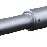
All indexable drills have one effective cutting geometry regardless of the number of inserts in the tool (usually two or four). Though both the inboard and outboard inserts seat in a neutral attitude in the drill, they have a 12° positive rake, which gives the drill a positive cutting geometry. The drill body’s 2 helical flutes evacuate chips efficiently and help prevent deflection of the drill. The flute helix angle on standard drill lengths varies with each drill size to provide the highest possible bending moment opposing the cutting forces. This increases drill stiffness, thereby minimizing chatter and deflection. Figure 1 depicts a cross section of a typical indexable drill.
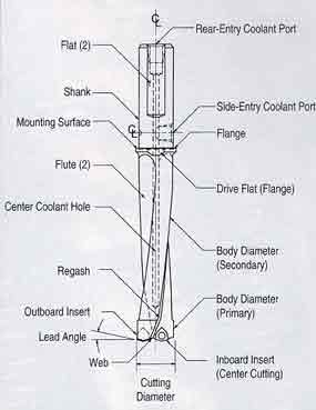 |
Figure 1: Indexable-drill nomenclature |
Tracking Footprints
The key to preventing tool deflection when using an indexable drill is to balance the cutting forces on each of the opposing inserts. The use of trigon inserts in indexable drills helps to ensure this balance. The trigon insert geometry stabilizes the drill in the cut, reducing tool deflection and improving penetration rates. Drills equipped with trigon inserts also are more versatile than those with conventional insert shapes. As illustrated in Figure 2, trigon-insert drills perform well in interrupted cuts and on a variety of workpiece surfaces, including flat, convex, concave, sloped, and irregular. Additionally, these tools can drill from solid, drill holes that are larger than the drill diameter, core drill, bore, and turn and face outer diameters when applied on a lathe.
A trigon-insert indexable drill leaves a well-defined pattern or “footprint” at the bottom of a blind hole or on the disk that is ejected from a through hole. This pattern is generated by the insert shape and the position of the drill. Examination of this footprint can reveal much about the drill’s performance.
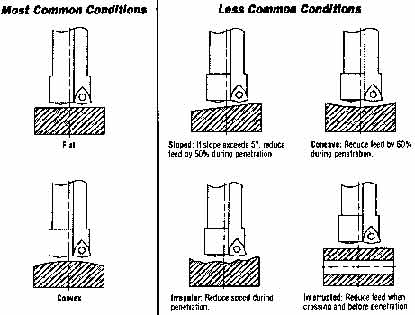 |
Figure 2: Indexable drills can machine holes in parts with a variety of nonflat surfaces. They can also bore and make interrupted cuts. |
On the disk or hole bottom, there is a stub surrounded by four distinct rings for double-insert drills. The outer two rings are generated by the outboard insert, while the inner two rings and the stub (ideally measuring 0.02″ in diameter and 0.01″ high) are created by the inboard or center-cutting insert.
The stub is created because the inboard insert station is positioned below center by 0.01″ radially. This positioning allows the inboard insert to cut past the center. If the stub measures 0.02″ in diameter, the drill is cutting to its designed diameter with little or no deflection (Figure 3a).
If there is no stub at all, it means the drill is either misaligned or deflecting oversize radially or axially, or a combination of the two (Figure 3b). When this happens, the inboard insert will probably chip at the drill’s centerline. This situation can be corrected by modifying the feed rate or realigning the drill.
If an overly large stub is present, it may mean that the inboard insert is being pulled off centerline radially or being pushed further behind center axially (Figure 3c). This condition will result in undersize holes and can be more damaging to the drill and inserts than if no stub were present.
To prevent these maladies, check all indexable drills for location with an indicator while in the machine tool. If the location varies by more than ±0.005″ TIR, then repositioning is necessary.
Chatter marks may also be present on the footprint, indicating that speeds and feeds should be modified. In most cases, increasing feed rates will eliminate chatter.
The finish of the rings also offers clues about the tool’s performance. At optimum speeds and feeds, the outer two rings cut by the outboard insert will be bright and the inner two will be dull.
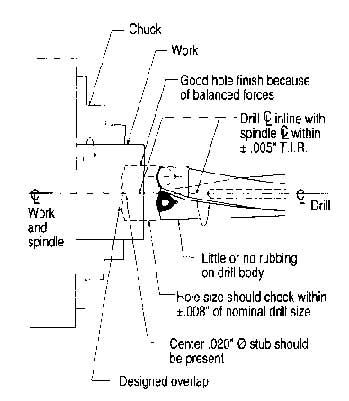 |
Figure 3a: An indexable drill machining a hole on-center. The result is a properly machined hole. |
Grade Points
Indexable drills require the inboard insert to cut past the centerline of the tool. As a result, the inboard insert experiences little or no sfm, which in turn heightens the compressive forces of the feed. For this reason, the inboard insert must be a tougher carbide grade than is required for its outboard counterpart. This means that two different carbide grades are required in most applications. Luckily for end users, there are plenty of grades available for indexable drill inserts.
When first introduced, indexable-insert drills were available with a limited selection of carbide-insert grades. Many drill manufacturers offered three grades of carbide: an uncoated C-1 grade for steel, coated C-7 for steel, and uncoated C-2 for nonferrous materials.
But today, many drill manufacturers offer a broad range of carbide grades for specific uses in high-performance applications. Many grades are custom-designed to machine a specific material or family of parts. Indexable-drill manufacturers may offer as many as 12 carbide grades, and in some cases they may even offer polycrystalline-diamond-tipped inserts for the high-speed drilling of aluminum.
Along with improvements in carbide grades, indexable drills have undergone advances in chipbreaker geometries developed to better control chips. Chip control is crucial to a successful drilling operation. The size and shape of a chip affects tool life, hole size, hole finish, and even the life of the drill body itself.
Almost all of today’s carbide inserts for indexable drills are pressed to form the general shape and then finish-ground to final size. Because of advances in pressing technology, an almost limitless variety of pressed-in chipbreaker shapes is possible.
Most of today’s manufacturers offer four or more chipbreaker configurations for machining various materials. There are two basic chipbreaker styles – standard and dimple.
Standard chipbreakers are designed for general-purpose drilling in short-chipping materials such as cast iron and in materials in which controllable chips can be produced by adjusting speeds and feeds. The standard chipbreaker is recommended for all steels with a hardness of Bhn 250 or higher, aluminum, all stainless steels, cast iron, and high-temperature alloys.
If changing parameters doesn’t result in controllable chips, you should try a dimple-style chipbreaker, which is designed to control chip formation in soft low-carbon steels, low-Brinell-hardness stainless steels, and any material that tends to create long, stringy chips with little or no color. (Colorless chips are the toughest to break.) The dimple form produces a chip that has ridges, which increase its brittleness. The ridges allow the chip to break more easily in softer materials.
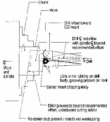 |
Figure 3b: An indexable drill machining oversize. |
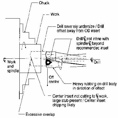 |
Figure 3c: An indexable drill machining undersize. |
Abandon Chips
Once the chip has been broken, the next challenge is to get it out of the hole. Poor chip evacuation can cause chip recutting, insert chipping, and even drill failure. The efficiency of chip evacuation depends upon chip control, coolant pressure, coolant volume, and hole depth. Figure 4 offers coolant guidelines for achieving optimum chip-evacuation efficiency.
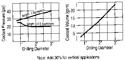 |
Figure 4: These graphs show recommended coolant volumes and pressures for various drilling diameters. |
In indexable drilling, it is imperative to remove the heat generated in the chip during the machining process, because indexable drills generate more heat than HSS or solid-carbide drills do. However, in drilling, the heat zone is a confined area at the bottom of the hole. Therefore, coolant acts as a carrier to transport both heat and chips from the bottom of the hole to the mouth of the hole through the flutes. For this reason, running indexable drills larger than 1 diameter without liquid coolant usually leads to drill failure. A full-flow water-base or synthetic coolant is generally recommended.
Many machine tool builders supply high-pressure, pulsating coolant systems with new machines. These coolant systems can generate pressures up to 300 psi, but they are limited to very low gpm ratings, usually a maximum of 5 gpm. At first glance, these systems, when combined with indexable tooling, appear to be highly efficient, but there are some disadvantages to consider:
- High-pressure systems are not capable of delivering gpm ratings up to indexable-drilling requirements. As a result, indexable-drill life suffers, even when coated inserts are used. Since the volume of coolant is insufficient, excessive heat will occur during the machining process.
- Pressures of 300 psi combined with a pulsating action can actually affect chip control and deflect the drill. The high pressures can flatten chips at the point of forming and force them back into the cut, causing chip recutting, insert chipping, and poor hole finishes.
- High pressures can force chips into clearance areas between the drill body and the hole wall. Chips will then wrap around the drill and become friction welded to either the drill body or the hole wall.
When applying indexable drills on high-pressure coolant systems, first try to push the coolant volume above 10 gpm. (If you can’t, you may need to peck-feed the drill.) Then reduce or discontinue the pulsator and run only with straight, constant pressure. Finally, reduce the pressure to 100-150 psi if possible.
Because of the importance of high-volume coolant delivery to the point of cut when using indexable drills, all indexable drills are manufactured having the largest coolant holes possible for a given drill diameter. This ensures that maximum coolant volume can be delivered to the cutting edge.
To help combat chip recutting, drill manufacturers are now offering indexable drills with two grooves on the end of the drill connecting the coolant holes to the drill flutes. Older drills that do not have this feature may have to be hand-ground. When grinding the grooves, make sure they aim at each insert as shown in Figure 5. The grooves should be half as deep as they are wide and should feature a full radius. The grooves will direct the coolant at the inserts, flushing the chips off the cutting edge as they are generated.
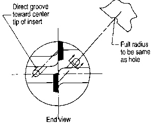 |
Figure 5: An end view of indexable-insert coolant grooves, which are designed to direct coolant at the inserts. |
When through-the-spindle coolant delivery is not possible, consider using coolant collars. These collars fit around the tool shank and have been engineered to operate within the drill’s speed guidelines. Always follow the manufacturer’s guidelines when installing a coolant collar, and make sure the external adaptation to the collar, either a pipe or a hose, is not binding the collar. Collar binding can cause premature failure or leakage. When using coolant collars, spindle speed should not exceed 3000 rpm and coolant pressure should not exceed 90 psi. The coolant must be well filtered, and the collar shouldn’t run dry.
|
Trouble-Shooting Guide |
||
|
Problem |
Source |
Solution |
|
|
||
| Insert chipping or breakage* | Off-center drill due to misalignment |
|
|
|
||
| Improper seating of tool in toolholder, spindle, or turret |
|
|
|
|
||
| Deflection due to excessive overhang or lack of rigidity |
|
|
| Improper seating of inserts in pocket |
|
|
|
|
||
| Damaged insert screws |
|
|
|
|
||
| Improper speeds and feeds |
|
|
|
|
||
| Improper coolant supply |
|
|
|
|
||
| Improper carbide grade in inboard station |
|
|
|
|
||
| Grooving on back stroke Drill body rubbing hole wall Overside or undersize holes |
Off-center drill |
|
|
|
||
| Deflection |
|
|
|
|
||
| Rough cutting action (tool rumbles and deflects | Too much thrust Feed rate too high |
|
|
|
||
| Recutting chips Feed rate too high |
|
|
|
|
||
| Poor hole surface finish | Vibrations |
|
|
|
||
| Insufficient coolant pressure and volume |
|
|
|
|
||
| Recutting chips causing drill to jump |
|
|
|
|
||
| Poor chip control Chips trapped in hole Chatter |
|
|
|
|
||
| Short, thick, flat chips | Feed rate too high in relation to cutting speed |
|
|
|
||
| Long, stringy chips | Feed rate too low in relation to cutting speed |
|
|
|
||
| Inability to loosen insert insert-locking screws | Seized threads due to coolant or heat |
|
Pushing the Limits
Some applications approach the limits of what indexable drills can do. Special care must be taken in these instances to ensure a successful operation. For instance, when applying indexable drills in deep-hole operations (greater than 4 diameters) or when entering a very rough or uneven surface, it may be necessary to halve the feed rate until the drill penetrates the workpiece to a depth of about 0.1″. This allows the drill to generate its footprint in the workpiece and create a clean, straight hole, and it helps eliminate insert chipping. The feed rate should also be halved when the drill exits surfaces that are uneven or rough to help prevent insert chipping.
As a general rule, it’s not a good idea to use indexable drills to make holes deeper than 4 diameters. Starting a long indexable drill in the cut is difficult, because the drill lacks rigidity, evacuating chips is a problem no matter what coolant system is used, and the tool is more likely to deflect. These factors add up to poor hole finishes.
Although an indexable drill generates approximately 30% fewer axial thrust pounds of force than a conventional HSS twist drill does, it still requires a very rigid machine tool and fixturing. If the spindle is not tight and properly adjusted, the drill will not perform as designed. The drill will cut off-center, resulting in oversize holes, poor hole finishes, and, in some cases, insert chipping. Similarly, an inadequately fixtured workpiece will render indexable drills ineffective, resulting in higher horsepower requirements and excessive axial thrust forces.
An indexable drill should not be applied to radial- or post-type drilling machines. Also, applying an indexable drill halfway up column-type machines can cause a severe loss of rigidity in the column, making it less able to resist axial thrust forces and torque forces generated when using indexable drills. Never apply the drill more than halfway up the column.
Also avoid using indexable drills to generate holes in laminated or stacked materials. Remember, all standard indexable drills produce a disk as the drill exits the hole, or in this case, as the drill exits one layer and enters the next. This disk becomes trapped between layers and causes severe tool damage or complete failure of the drill. The latter is more likely.
Outside of these specific circumstances, indexable drills represent a highly efficient and versatile drilling technology, offering the advantages of carbide at a reasonable cost.
Indexable Carbide Drills Reduce Roughing Time 85%
Usually, before a shop purchases a new kind of tool, it tests the tool under the most challenging machining conditions the shop has to offer. Progressive Tool Co., Waterloo, IA, offered such a challenge to a new indexable carbide drill.
The majority of Progressive Tool’s business is in the design, machining, and assembly of precision stamping dies for a variety of industries. One of the firm’s jobs, a mold for a major customer, was causing great difficulty. The workpiece was a 4″-thick block of A-2 tool steel, which has a hardness of Rc 30. A-2 tool steel’s stringiness makes it difficult to machine.
The operation required 180 1″-dia. through holes. Tolerances and surface finish were not critical, because this was strictly a roughing operation. Progressive Tool’s concern was to remove material more quickly and more efficiently than its current process allowed.
The steel block was initially run with an HSS twist drill and required three separate operations to complete each hole. First, each hole had to be spot drilled. Next, a 13¼32″ pilot hole was drilled through. Finally, a 1″ HSS twist drill was used to complete the roughing operation.
Overall, these three operations resulted in a cycle time of 8 min., 15 sec./hole. Multiply that by 180 holes, and the total is 25 hr. of machining time for a simple roughing operation.
This inordinate amount of machining time, along with inadequate tool life, made the HSS tool’s performance unsatisfactory. Progressive Tool had to look for an alternative method of performing the roughing operation.
Progressive Tool was aware of indexable carbide drills’ capabilities and decided to test the tool on the troublesome production piece so that engineers could directly compare the HSS and indexable drills.
As per standard procedure, the speeds and feeds were turned down to 60% as the test began. When the tool first made contact with the test block, it seemed to run roughly. On successive holes, the speeds and feeds were gradually increased. The indexable drill ran more smoothly as the overrides were increased. Finally, at 150% of the programmed speeds and feeds, the drill ran smoothly and consistently through the entire 4″ cut.
Progressive Tool noted several advantages of the indexable drill. It replaced three separate operations using three separate tools with a single operation requiring only a single tool. This reduced setup time and tool and hardware inventory. In addition, the feed rates were increased from 2.0 ipm with HSS drills to 3.6 ipm with indexable drills.
The roughing operation was completed in 1 min., 18 sec./hole using the indexable drill. Multiply this by 180 holes, and the total time for this operation was 3.9 hr., compared to 25 hr. using the HSS drill. That’s an 85% cycle-time reduction.
Tool life was improved as well. The inserts lasted for 25 holes before they required indexing. The indexable drill went through 100″ of A-2 tool steel before the operation had to be stopped, as compared to 60″ with the HSS drill (not including the pilot drill). Even then, it was a quick and easy task to index the inserts and restart the run.
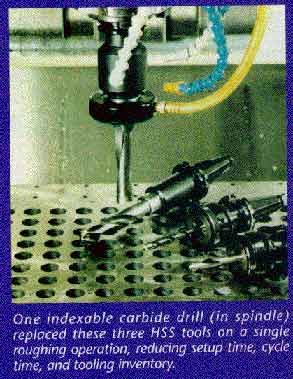 |
Figure 6: One indexable carbide drill (in spindle) replaced these three HSS tools on a single roughing operation, reducing setup time, cycle time, and tooling inventory. |
“There is almost no load put on the spindle,” notes Progressive Tool foreman Bruce Erpelding. “The load meter barely moves off its idle reading. When we used HSS drills, it was common to run the load meter to 60% and kick out the overload.” The reduction in spindle load saves wear and tear on the spindle and bearings.
When HSS tooling was used, Progressive Tool had to use a peck drilling cycle to break up the chips. The operator had to remain dedicated to a single machine to be sure the cycle ran properly. With the indexable drill, the chips are small and manageable. The operator does not have to monitor the cycle as closely and therefore is free to run another machine as well. Also, the smaller chips are safer for the operator to handle.
About the Author
Thomas Benjamin is a product manager with Ingersoll Cutting Tool Co., Rockford, IL.


MFGAxis Discussion