Getting a Better Edge: Design & Engineering
The author, an expert on cutting tool edge preparation, explains the importance of applying the proper edge hone to a tool.
Most cutting edge hones are 0.003″ to 0.001″, which makes them difficult to apply.
All photographs by Ernie Sistek Jr.
The list of variables affecting carbide cutting tool performance is long and well-documented. It ranges from tool-based attributes such as carbide grade to process-based ones like spindle stiffness. Buried on this list is a seldom-discussed variable—edge geometry.
The act of applying an edge geometry to a tool is sometimes referred to as “edge preparation,” and the process is generically termed “edge honing” or, simply, “honing.” Edge prepping is done a number of different ways: vibratory honing, honing by hand with diamond stones, media honing, slurry honing, honing with media-impregnated rubber wheels, dry and wet blasting, tumbling and brush honing.
The primary purpose of honing is to establish the interface between the tool and the workpiece. Chip flow, cutting speed, in-feed pressure and other machining variables are strongly impacted by the characteristics of this interface. The size and shape of the hone determine the amount of tool pressure required for a machining operation to be successful.
If the hone is too large for a given application, the excessive pressure required to cut will increase the amount of heat developed during machining. That shortens tool life. Conversely, if the hone is too small, the cutting tool edge will be weak and unable to withstand cutting pressures.
Although the benefits of honing have been understood for many years, the process has not been fully controlled and tool performance has suffered as a result. Even with today’s ultraprecise cutting tools, users still experience problems related to incorrect edge geometry.
Size Matters

Before Honing
After Honing
A properly honed cutting edge is a uniformly distributed, rounded-edge preparation that is accurate in size and specific in geometric shape.
It’s important to realize that all aspects of edge honing are microscopic in nature. The majority of honed edges—perhaps 70 percent—are in the range of 0.003″ to 0.001″ or smaller. (A human hair is approximately 0.003″ in diameter.) Other hones, depending on the application, can range from less than 0.0005″ to as large as 0.008″. A small edge hone can be one-sixth the thickness of a hair.
Within these size ranges are process tolerances. A hone size specified at 0.001″ to 0.003″, for example, requires all honed cutting edges of the tool to fall within that tolerance range. Furthermore, because edge honing is an erosive process and all cutting tool materials are highly resistant to wear, controlling the material-removal rate and keeping the honed edge uniform can be a monumental task.
Given these facts, it’s understandable why tool manufacturers can easily miss the target hone size. When they miss the mark by even a miniscule amount, they can produce tools that vary significantly in terms of usable life. And if they miss the hone target by 0.001″—or one-third the thickness of a human hair—the tool may not perform at all.
Edge-Prep ‘Edge’
A properly honed cutting edge is a uniformly distributed, rounded-edge preparation that is very accurate in size and specific in geometric shape. Its purpose is to maximize the cutting tool’s edge strength and performance.
The benefits of proper edge preparation include the following:
Longer tool life. A carbide cutting tool’s edge must withstand tremendous stress. Its ability to handle the applied stress and wear in a slow, predictable manner determines a tool’s life and wear rate. Tool life is largely determined by the workpiece material. In certain applications, proper edge preparation has improved tool life 200 percent or more.
Greater consistency. Without a consistent process for applying edge geometry, tool life will vary from tool to tool. This makes unattended machining extremely difficult. Among the dividends of predictable tool performance are greater productivity, reduced scrap and less rework.
Enhanced workpiece finish. Typically, workpiece surface finish is a function of the size of the tool’s corner radius, the depth of cut and the feed rate. One of the benefits of a consistent, smooth edge is that it reduces the tendency of a tool to microchip (small pieces of the cutting tool coating and substrate break away during machining). These chips create an inconsistent edge that degrades the finish and shortens tool life. Another condition that can drastically undermine surface finish is built-up edge. BUE develops on a cutting tool for several reasons, but at least one is related to the edge hone. If the edge hone is incorrectly sized and insufficiently smooth, small workpiece pArticles can attach to the cutting edge. If this buildup continues, more and more material will attach to the tool. Eventually, the operator will have to stop the operation because surface finish has been adversely affected, or because he’s lost part-size control. If the BUE breaks away during machining, it’s likely that a portion of the tool coating—and perhaps the substrate—will break off as well.
Most tools coated by the chemical-vapor-deposition process have a rounded or honed edge. They receive an edge prep prior to coating primarily to give the thicker CVD-type coatings an adequate surface to bond to.
Typically, CVD-coating thickness varies from 6 to 8 microns, depending on the coating composition and tool application. CVD coatings also tend to build out and away from a sharp-cornered cutting edge. Because of this, the coating on the corner of the cutting edge can be more than 50 percent thicker (9 to 12 microns) than on other areas of the tool. Such an edge, comprised only of thick coating material unsupported by the tool substrate, will form an extremely weak cutting edge. It will not withstand normal cutting pressures.
Physical-vapor-deposition coatings, on the other hand, are comprised of very thin layers whose total thickness is 1 to 5 microns. They are less likely to build up on a sharp corner than coatings applied by the CVD process, which is one reason PVD-coated tools are often left unhoned.
However, there seems to be a growing interest among cutting tool users to have small hones—0.0005″ and smaller—applied to PVD-coated tools. Even that small of an edge hone can significantly strengthen a tool.
Hone Sizes, Types
The size of a tool’s hone is critical to its performance. Larger hones make the edge stronger and capable of withstanding greater pressures in applications involving heavy DOCs or interrupted cuts. Smaller hones play an important role in workpiece finish and help prevent heat buildup in applications with lighter in-feed pressures.
As a rule, smaller hones are preferable because they leave more material on the cutting edge, which effectively extends tool life.
The geometric shape of the edge hone affects tool performance just as much as hone size does. The radius-shape hone is, overwhelmingly, the preferred choice (Figure 1). More than 80 percent of honed cutting tools receive a radius hone, which is centrally located on the cutting corner of the tool. This hone forms a true circular shape that blends equally with the top surface of the tool and the tool’s flank, or side.
With a waterfall-shaped hone, the edge prep is skewed toward the top side of the tool (Figure 2). The ratio of the top side of the edge to its side is normally 2:1. The main benefit of a waterfall hone is that the honing process leaves more tool material directly under the cutting edge, which further strengthens the corner.
Waterfall hones are mostly used for very rough machining applications, such as those involving interrupted cuts or removing scale from a workpiece. In most heavy cutting applications, a tool with a waterfall hone will outperform one with a radius hone. However, for most standard cutting applications—those that warrant a radius edge—the use of a waterfall edge would increase tool pressure and shorten tool life.
Machine Designer Takes the Plunge
The designer of the Conicity IXM-50 honing machine, Bill Shaffer, said that his decision to start his own company approximately two years ago “could have been viewed as a headfirst dive into a rock-filled lake. My decision came at a time when the entire cutting tool industry was just beginning a worldwide slowdown.”
But the 51-year-old engineer plunged in anyway. Shaffer ended his 30-year career at cutting tool manufacturer Kennametal Inc. and opened Solo Solutions, a manufacturing consulting firm. During a question-and-answer session, he talked about his decision and the idea behind his honing machine.
CUTTING TOOL ENGINEERING: Why did you open Solo Solutions?
Bill Shaffer: About two years ago, I decided that I would fulfill a promise I had made to myself to establish my own business. I had a very successful career in which I occupied a wide array of engineering positions within one company. My career [at Kennametal] culminated with my working as a corporate-level engineering manager. One of the factors that helped me make the decision to begin a new career came after the completion of a project I worked on in Shanghai, China. The satisfaction I derived from the experience reinforced my desire to move into manufacturing consulting as a primary vocation. The promise to start my own business also included a personal benchmark of making this move before I was 50. So, at the age of 49 years and 11 months, and with the help of my wife, Mary Ann, I refocused my life.
CTE: Where did the idea for the honing machine come from?
Shaffer: I launched my business after visiting several large-scale insert manufacturing companies and offering my services. It was during those initial visits that I discovered that nearly all of the cutting tool fabricators had similar challenges when it came to the process of edge preparation. There were opportunities to improve hone consistency and uniformity. There also were opportunities to cover the full range of cutting tool materials, not just some of the materials. And the existing honing processes were developed to only handle certain geometric shapes—not a variety. The industry needed a single honing system able to handle all cutting tool materials and geometric shapes.

Shaffer took the IXM-50 from concept to fully operational machine in six months.CTE: So you decided to manufacture such a system.
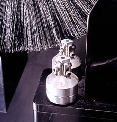
Shaffer: Right. I realized that edge preparation is a critical process for all insert fabricators in the world, large and small. I viewed this as a great business opportunity. I already had a 20-year background in edge preparation and was intimately familiar with all the machines and processes that are commercially available. (Twenty years ago, Shaffer was responsible for the initial breakthrough of using abrasive nylon-filament brushes for edge preparation.) My background, coupled with my understanding of the requirements of a finished tool, gave me a huge advantage. It let me move quickly toward developing a solution to many edge-honing problems.
CTE: Tell us about developing the machine.
Shaffer: I began to test and evaluate using a bench-scale model of a brush-honing machine that I constructed in a machine shop. Although visually it was very crude, it allowed me to manipulate all the variables associated with brush honing. After approximately one month of testing, I was certain that I had found the cure to a lot of the inherent inaccuracies plaguing traditional brush-honing edge preparation. From that point, I continued to collect data and then set about designing a machine. It took six months from the actual concept date to build a fully operational honing machine.
CTE: Is the machine in production?
Shaffer: Everything is in place for production. Because we’re a small company, we don’t have machines sitting on the shelf. We can build a machine in six to eight weeks.
CTE: Have you sold any?
Shaffer: No. The machine just assumed “for-sale” status the first of January.
CTE: What has been the level of interest in the machine?
Shaffer: Very high. All the major tool manufacturers in the world have been exposed to it, either by an actual demonstration or seeing a pamphlet describing it or a video of the machine in operation.
CTE: You say that the IXM-50 is relatively low in price. What does that mean in dollars and cents?
Shaffer: The base price of the machine is just under $100,000. Other CNC edge-prep machines on the market today cost as much as $400,000 to $500,000.
CTE: How do you sell a machine for that price while claiming that it has the same capabilities as more expensive machines?
Shaffer: Actually, my machine has better capabilities. Its design revolves around the correct application of the abrasive filament brush, as specified by the brush manufacturer. Proper brush application permits a reduction in the size of the machine and reduces the need for heavy components. In fact, I use a Lista tool cabinet with drawers for the base of the IXM-50. Proper application of the brush also eliminates the need for coolant during processing.
– Don Nelson
A Better Edge
The technology of tool edge preparation has not advanced as rapidly as technologies related to the other components of cutting tools, such as material substrate, geometry and coating. And although each manufacturer has an established process for honing different types of tools, creating edge geometries remains more art than science. Consequently, edge-prep tolerances are generally wide and quality deviations are common.
Because edge honing is an erosive process performed on a microscopic scale, total process control is required to hold extremely tight tolerances. However, none of the current methods of edge honing provides this control.
Consider an edge requiring a 0.0005″ hone. If one of the processes mentioned earlier in the article were used to apply the hone, one spot on the tool may meet the 0.0005″ specification, but the remainder of the edge may vary above or below that size by 100 percent or more.
To correctly and uniformly apply a 0.0005″ hone on all of a tool’s cutting edges, the process parameters must be controlled to such a degree that material removal automatically stops when the desired hone size is achieved. That’s accomplished in brush honing when the correct abrasive media is combined with controlled surface exposure, brush-contact time and brush speed.
One machine capable of this type of control is the newly developed Conicity IXM-50 honing machine, manufactured by Conicity Technologies LLC. Because the machining parameters are controlled via CNC programming, the IXM-50 essentially stops removing material when the correct hone size is achieved.
‘Lean’ Concept Behind Machine’s DesignThe Conicity IXM-50 honing machine was designed to embody the lean-manufacturing philosophies that are the cornerstone of current manufacturing strategies. In other words, the aim was to develop a machine able to reduce production-related costs, improve part quality and shorten lead times.
The following summarizes the IXM-50’s most salient features:
The IXM-50 can edge-prep nearly all tool geometries in virtually any material.Small size. In order to aid the development of integrated production operations, the machine was designed to be as small as possible. It’s approximately 75 percent smaller than other systems. The machine’s size facilitates its use in a manufacturing cell that combines grinding and honing operations.
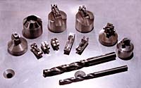
Flexibility. Other systems are limited to producing specific geometries and honing certain types of cutting tool materials. The IXM-50 can edge-prep nearly all tool geometries in virtually any material.
Quick setups. Machines do not make money when they are being set up. They make money when they turn out products. The IXM-50’s quick-change tooling lets the operator change brushes and swap out one type of cutting tool for another without using hand tools. Most changeovers can be made in two minutes and require the operator to input a few simple commands.
Additionally, the new machine’s compatibility with lean-manufacturing philosophies could benefit users by allowing tool manufacturers and service subcontractors to customize hone geometries for specific metalcutting applications.
– W. Shaffer
An additional feature of the machine is its ability to intentionally produce edge hones of varying sizes on separate surfaces of the same tool. Other honing processes can’t do this. Potential applications for variable honing are grooving tools and thread chasers.
Consider a straight-ahead plunge-style grooving tool. A variable hone would expand this tool’s cutting capabilities. Normally, a uniform hone is applied to the front end of the tool and to its adjacent sides. The Conicity IXM-50 lets the machine operator take the same grooving tool and hone its adjacent sides so that they’re smaller than the nose. The upshot is that a tool originally designed solely for straight-plunge machining could be used to make light lateral cuts.
Figure 1: More than 80 percent of honed cutting tools receive a radius hone, which is centrally located on the cutting corner of the tool. Tools with this type of hone are used for general applications. Figure 2: With a waterfall-shaped hone, the edge prep is skewed toward the top side of the tool. The main benefit of a waterfall hone is that the honing process leaves more tool material directly under the cutting edge, which further strengthens the corner.
Variable honing can turn thread chasers into combination roughing/finishing tools. A thread chaser is normally presented to the workpiece in a right-to-left feeding direction. Because of this action, the left side of the tool removes more material as it moves through the cut than the right side does. The right, or trailing, side is responsible for finishing the thread form and controlling its size. Considering how a thread chaser functions, it would be beneficial to have the hone size larger on the feeding side of the tool and smaller on the trailing edge, which establishes surface finish and size.
The Conicity machine can produce a uniform hone on the thread-cutting surfaces while gradually reducing the size of the hone as it moves from one end of the tool to the other. With the hone applied in a tapering fashion, the thread chaser becomes a combination roughing and finishing tool.
Who Gains?
The ability to apply precise edge geometries will never substitute for having complete control over all the variables that affect a machining operation. But producing precise edge geometries can offer significant benefits.
For tool users, these benefits would mostly be economic. Edge geometry affects tool performance in two specific ways. First, it heavily influences tool reliability. Properly honed tools can improve the repeatability of machining operations, assisting the drive toward “lights-out” manufacturing. Second, correct edge preparations improve tool life by reducing the common causes of failure, such as chipping, heat-induced failure and BUE.
While improved tool life and reliability are certainly attractive, enhancing the performance of existing tools is only part of the story. Perhaps the greatest benefit of the new honing technology will be in the field of tool development. Having ultraprecise control over the cutting edge—the tool/workpiece interface—will enable toolmakers to offer products that perform at previously unobtainable levels.
About the Author
William Shaffer is the designer of the Conicity IXM-50 honing machine, as well as president of Solo Solutions, Greensburg, Pa., and executive vice president of Conicity Technologies LLC, the Cresco, Pa., company that manufactures the IXM-50. Shaffer has more than 30 years’ experience in the cutting tool industry.

MFGAxis Discussion