Several machine tool builders have taken root there over the past decade. These companies share at least one characteristic: They all specialize in finding creative solutions to known problems. Their work has earned the region a reputation as a source of innovative equipment.
Among these self-made Valley men stands Ed Freer, proprietor of Freer Engineering, Simi Valley, Calif. Ask Freer for credentials, and he points to a wall in the room next to his office. There, hanging in 13 frames, are the patents that attest to this inventor’s creative use of technology in a number of disciplines. He has designed assembly machines for the electronics industry, a machine that inserts tips into ballpoint pens, and measuring equipment.
Freer’s biggest contribution to metalworking is his micromachining center. Dubbed the SM-2000, the machine can be used to produce miniature parts in small lot sizes from a variety of difficult-to-machine materials (Figure 1). And once a shop is satisfied with the prototypes and short-run parts coming off the machine, the SM-2000 can shift into high gear to become an effective production machine.
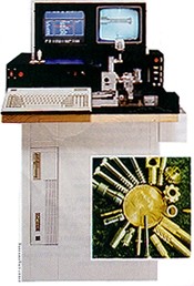
Figure 1: The SM-200 uses PC-based controls ans a video system to aid in the manufacture of miniature parts. Inset: The SM-2000 can be used at every stage of prototyping and production for small parts such as these.
The SM-2000 grew out of Freer’s efforts in the 1980s to design a machine for the fabrication of miniature medical parts. Some manufacturers make small parts with equipment such as screw machines, but these machines cannot produce a small run of parts economically. And a machining center might be used for short runs, but it does not offer a magnified view of the part for setup and prototyping work.
Freer’s answer was the SM-2000. “I call it a smart machine because the computer has all the information required for the machine to work stored in its master file,” Freer said. With such information close at hand, an operator can program an application simply by assembling individual operations from the blueprint.
Chief among the machine’s problem-solving innovations is its PC-controlled video monitoring and inspection system. Freer’s prior experience designing measuring equipment had taught him that users would accept viewing small parts with a video system much faster than they would take to any other type of technology.
“Nobody would take the time to learn how to use a microscope,” he said.
Simplicity Designed In
In one departure from many other machines, Freer gave the SM-2000 PC-based controls with a standard library of functions already programmed and installed instead of a CNC. By calling up these functions, an operator can automatically execute any machining
operation without additional mathematics or machining instructions. The only data that must be input for each operation are the travel distance, the speed and the feed rate.
The operator uses conversational programming to enter this information at the machine, choosing from menu options such as “turn,” “saw slot” or “cutoff.” The SM-2000 is equipped with a drill, a turning tool, a double-drill, a cutoff tool, a boring tool, a roller tool, an offset-drilling tool and a saw (Figure 2). These are standard miniature carbide tools. With a combination of tools and programming, the machine can perform a wide variety of operations, including turning, drilling, milling, rolling, crimping, broaching, knurling and cutoff.
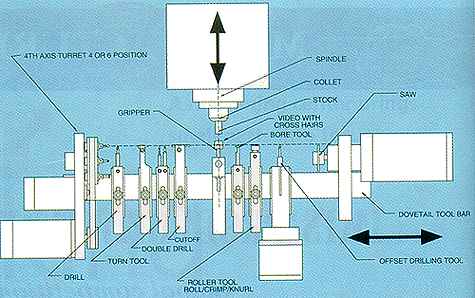
Figure 2: Among the operations the SM-2000 can perform are drilling, milling, turning, sawing, crimping and broaching. The machine comes equipped with all the standard miniature carbide tools shown.
With some relatively easy programming steps and a standard single-point cutting tool, an operator can even produce special, complex threads or knurl the inside diameter of a part. An auxiliary spindle on the 4th axis eliminates the need for many secondary operations.
The operator premounts the cutting tools inline on the machine. Once the tools are mounted, the operator assigns them positions so the computer will know the locations of their centerlines and edges. To locate each tool, the operator uses a joystick to move the table. With the tool aligned in the X-Y coordinate cross hairs on the video screen, the operator makes a few keystrokes to establish the tool’s location in relation to the workpiece’s centerline and its end. After all the tools’ locations have been established, the operator enters the machining dimensions to create the tool paths. Each machining step is programmed in sequence.
To cut a thread, for instance, the operator first uses the menu to ask for the threading tool. Then he or she defines the thread dimensions and, finally, establishes the thread termination. Once the prototype program has been listed and tested, the machine is ready to operate automatically. The operator simply enters the number of parts to be produced and the machine becomes an automatic production center.
Simple Success
Among the users who value the SM-2000’s uncomplicated operation is Rob Whitmore, president of Medical Micro Machining Inc., Simi Valley. “For short runs or prototyping, the SM-2000 is simple and easy to use compared to more complex machines like the Swiss automatics,” he said. “The video screen makes it easy to see what you are doing at all times.”
Whitmore claimed that he can train people with no machining experience to produce parts on the SM-2000 that an experienced operator would find impossible to produce on a standard CNC machine.
In Admore, Okla., the SM-2000 helped Imtec-Swiss Corp. earn the state’s Innovator of the Year honor. The company’s manufacturing engineer, Steve Hadwin, said the machine’s ability to produce very small parts with a few simple programming steps proved invaluable. “Even a 0.060"-ID thread is no problem,” he claimed, “and, most importantly, the video screen makes it easy to see parts as they’re run.”
Remmele Engineering, Big Lakes, Minn., uses the SM-2000 to shave time off of its prototyping schedule. For one prototyping project, the company was able to complete programming, setup and proof runs for four parts in three days. Typically, such a project would have taken a month to complete.
“Today, time to market is everything,” said Dean Broberg, a Remmele manufacturing engineer. “With the SM-2000, we can turn out proof-of-concept parts in a day. This is a tremendous competitive advantage.”
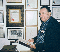
Ed Freer stands before the 13 patents he holds for machine designs. His inventions include assembly machines for the electronics industry, a machine that inserts tips into ballpoint pens, and measuring equipment.
Related Glossary Terms
- boring
boring
Enlarging a hole that already has been drilled or cored. Generally, it is an operation of truing the previously drilled hole with a single-point, lathe-type tool. Boring is essentially internal turning, in that usually a single-point cutting tool forms the internal shape. Some tools are available with two cutting edges to balance cutting forces.
- broaching
broaching
Operation in which a cutter progressively enlarges a slot or hole or shapes a workpiece exterior. Low teeth start the cut, intermediate teeth remove the majority of the material and high teeth finish the task. Broaching can be a one-step operation, as opposed to milling and slotting, which require repeated passes. Typically, however, broaching also involves multiple passes.
- computer numerical control ( CNC)
computer numerical control ( CNC)
Microprocessor-based controller dedicated to a machine tool that permits the creation or modification of parts. Programmed numerical control activates the machine’s servos and spindle drives and controls the various machining operations. See DNC, direct numerical control; NC, numerical control.
- conversational programming
conversational programming
Method for using plain English to produce G-code file without knowing G-code in order to program CNC machines.
- cutoff
cutoff
Step that prepares a slug, blank or other workpiece for machining or other processing by separating it from the original stock. Performed on lathes, chucking machines, automatic screw machines and other turning machines. Also performed on milling machines, machining centers with slitting saws and sawing machines with cold (circular) saws, hacksaws, bandsaws or abrasive cutoff saws. See saw, sawing machine; turning.
- feed
feed
Rate of change of position of the tool as a whole, relative to the workpiece while cutting.
- gang cutting ( milling)
gang cutting ( milling)
Machining with several cutters mounted on a single arbor, generally for simultaneous cutting.
- knurling
knurling
Chipless material-displacement process that is usually accomplished on a lathe by forcing a knurling die into the surface of a rotating workpiece to create a pattern. Knurling is often performed to create a decorative or gripping surface and repair undersized shafts.
- machining center
machining center
CNC machine tool capable of drilling, reaming, tapping, milling and boring. Normally comes with an automatic toolchanger. See automatic toolchanger.
- metalworking
metalworking
Any manufacturing process in which metal is processed or machined such that the workpiece is given a new shape. Broadly defined, the term includes processes such as design and layout, heat-treating, material handling and inspection.
- milling
milling
Machining operation in which metal or other material is removed by applying power to a rotating cutter. In vertical milling, the cutting tool is mounted vertically on the spindle. In horizontal milling, the cutting tool is mounted horizontally, either directly on the spindle or on an arbor. Horizontal milling is further broken down into conventional milling, where the cutter rotates opposite the direction of feed, or “up” into the workpiece; and climb milling, where the cutter rotates in the direction of feed, or “down” into the workpiece. Milling operations include plane or surface milling, endmilling, facemilling, angle milling, form milling and profiling.
- sawing
sawing
Machining operation in which a powered machine, usually equipped with a blade having milled or ground teeth, is used to part material (cutoff) or give it a new shape (contour bandsawing, band machining). Four basic types of sawing operations are: hacksawing (power or manual operation in which the blade moves back and forth through the work, cutting on one of the strokes); cold or circular sawing (a rotating, circular, toothed blade parts the material much as a workshop table saw or radial-arm saw cuts wood); bandsawing (a flexible, toothed blade rides on wheels under tension and is guided through the work); and abrasive sawing (abrasive points attached to a fiber or metal backing part stock, could be considered a grinding operation).
- sawing machine ( saw)
sawing machine ( saw)
Machine designed to use a serrated-tooth blade to cut metal or other material. Comes in a wide variety of styles but takes one of four basic forms: hacksaw (a simple, rugged machine that uses a reciprocating motion to part metal or other material); cold or circular saw (powers a circular blade that cuts structural materials); bandsaw (runs an endless band; the two basic types are cutoff and contour band machines, which cut intricate contours and shapes); and abrasive cutoff saw (similar in appearance to the cold saw, but uses an abrasive disc that rotates at high speeds rather than a blade with serrated teeth).
- threading
threading
Process of both external (e.g., thread milling) and internal (e.g., tapping, thread milling) cutting, turning and rolling of threads into particular material. Standardized specifications are available to determine the desired results of the threading process. Numerous thread-series designations are written for specific applications. Threading often is performed on a lathe. Specifications such as thread height are critical in determining the strength of the threads. The material used is taken into consideration in determining the expected results of any particular application for that threaded piece. In external threading, a calculated depth is required as well as a particular angle to the cut. To perform internal threading, the exact diameter to bore the hole is critical before threading. The threads are distinguished from one another by the amount of tolerance and/or allowance that is specified. See turning.
- turning
turning
Workpiece is held in a chuck, mounted on a face plate or secured between centers and rotated while a cutting tool, normally a single-point tool, is fed into it along its periphery or across its end or face. Takes the form of straight turning (cutting along the periphery of the workpiece); taper turning (creating a taper); step turning (turning different-size diameters on the same work); chamfering (beveling an edge or shoulder); facing (cutting on an end); turning threads (usually external but can be internal); roughing (high-volume metal removal); and finishing (final light cuts). Performed on lathes, turning centers, chucking machines, automatic screw machines and similar machines.