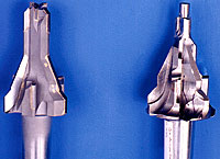
At left is the six-in-one tool with inserts in place. The tool at the right is in the "as-milled" state. The design of the tool has evolved over a period of time.
A dedicated production machine can consistently outproduce a multitask CNC machine. But while a dedicated machine is able to maintain high production rates during lengthy part runs, flexibility is generally sacrificed for speed.
That’s the case at Caterpillar’s Lafayette, Ind., plant. The manufacturer of heavy equipment produces its 3500-series gray cast iron cylinder heads on a transfer line. The cored holes of the cylinder’s valves are machined at dedicated drilling stations that run at a fixed speed and a fixed feed rate.
Over time, design changes to the cylinder head have required more features to be added to the cored holes. One of Caterpillar Tooling Engineer Russell Shoemaker’s jobs has been to find ways to make the same fixed-speed drilling stations produce multiple-diameter holes that are chamfered and spotfaced. This has required him to utilize tools with increasingly complex designs.
He’s gotten help from Hartland Cutting Tools Inc., Cary, Ill., a custom-tool maker specializing in subland drills. The long-term partnership between the companies has resulted in a highly evolved multidiameter tool that completes six operations in a single pass.
Design Limitations
Unable to modify Shoemaker’s speed and feed specifications, Hartland had to create a design that would compensate for these fixed parameters. The dedicated drill stations operate at a fixed speed of 700 rpm and a fixed feed rate of 0.010 ipr, presenting a significant design challenge for Hartland Engineering Manager Rick Lucchetti. Plus, Caterpillar required that the tool make 800 holes between resharpenings.
This unique multidiameter cutting tool’s body is made from M-7 HSS that’s heat-treated to RC 63. It incorporates a No. 3 Morse taper to accommodate the existing holders in Caterpillar’s dedicated machinery.
The tool’s body also features six subland-style flutes. The cutting edges for the multiple features are located along these flutes, at various depths.
In operation, the first job the tool performs is to cut a 0.748"-dia. spotface at the bottom of the 3"-deep cored hole. The spotface prepares the surface to accept a G-drill—also known as a square drill—which is applied at a subsequent drilling station.
Previous versions of the multidiameter tool incorporated solid-carbide cutting edges for each feature. But the fixed speed of 700 rpm only provided about half the required surface footage for the 0.748"-dia. spotfacing geometry. Running carbide slower than the recommended surface footage results in premature failure of the cutting edge.
When test-machining cylinder heads supplied by Shoemaker, Lucchetti found that the spotfacing portion of the tool lasted just 400 holes, or half of the production requirement. He solved the problem by grinding an uncoated spotfacing geometry directly into the HSS tool body. An HSS cutting edge is more effective than carbide at a slower surface footage—in this case, 136 sfm.
The HSS spotfacing feature allows the multidiameter tool to drill 1,200 cored holes with no visible signs of wear on any of the cutting edges. The remaining geometries of the tool were left unchanged.
The tool feature that follows the spotface geometry creates a 45° chamfer in a 1.140"-dia. bore that’s 0.875" deep. The next feature cuts a 25° chamfer to a depth of 1.000" in a bore with a 2.259" diameter and a depth of 0.350". The final cutting edge produces another 45° chamfer. The final carbide edge, which spans the diameter of the cored hole, cleans up any slight variations that occur during the casting process.
Divide and Conquer
The multidiameter tool divides the cutting edges along six subland-style flutes. The first set of three flutes, spaced 120° apart, have cutting edges ground directly into the end of the HSS tool body; these edges cut the 0.748" spotface. Carbide cutting edges brazed onto the flutes complete the 1.140" bore. The remaining three flutes bisect the first set of flutes and contain brazed-on carbide cutting edges that perform the remaining operations. The subland design distributes pressure that develops across the entire tool body, resulting in increased tool life.
The rough machining of the flutes, relief angles and pockets for the carbide cutting edges were accomplished on a Mazak VTC 20B CNC vertical machining center with a Nikken 4th-axis rotary table. The machining program was developed manually in about 12 hours using Mazatrol conversational language. The first four tools produced for Caterpillar had an unattended machining time of approximately one hour, a significant improvement from the six hours of manual milling needed when the prototype was produced.
Lucchetti believes that the cycle time will be as low as 40 minutes per tool when Hartland begins producing the 150 tools that Caterpillar expects it will need in 2000.
Related Glossary Terms
- computer numerical control ( CNC)
computer numerical control ( CNC)
Microprocessor-based controller dedicated to a machine tool that permits the creation or modification of parts. Programmed numerical control activates the machine’s servos and spindle drives and controls the various machining operations. See DNC, direct numerical control; NC, numerical control.
- feed
feed
Rate of change of position of the tool as a whole, relative to the workpiece while cutting.
- flutes
flutes
Grooves and spaces in the body of a tool that permit chip removal from, and cutting-fluid application to, the point of cut.
- gang cutting ( milling)
gang cutting ( milling)
Machining with several cutters mounted on a single arbor, generally for simultaneous cutting.
- grinding
grinding
Machining operation in which material is removed from the workpiece by a powered abrasive wheel, stone, belt, paste, sheet, compound, slurry, etc. Takes various forms: surface grinding (creates flat and/or squared surfaces); cylindrical grinding (for external cylindrical and tapered shapes, fillets, undercuts, etc.); centerless grinding; chamfering; thread and form grinding; tool and cutter grinding; offhand grinding; lapping and polishing (grinding with extremely fine grits to create ultrasmooth surfaces); honing; and disc grinding.
- high-speed steels ( HSS)
high-speed steels ( HSS)
Available in two major types: tungsten high-speed steels (designated by letter T having tungsten as the principal alloying element) and molybdenum high-speed steels (designated by letter M having molybdenum as the principal alloying element). The type T high-speed steels containing cobalt have higher wear resistance and greater red (hot) hardness, withstanding cutting temperature up to 1,100º F (590º C). The type T steels are used to fabricate metalcutting tools (milling cutters, drills, reamers and taps), woodworking tools, various types of punches and dies, ball and roller bearings. The type M steels are used for cutting tools and various types of dies.
- machining center
machining center
CNC machine tool capable of drilling, reaming, tapping, milling and boring. Normally comes with an automatic toolchanger. See automatic toolchanger.
- milling
milling
Machining operation in which metal or other material is removed by applying power to a rotating cutter. In vertical milling, the cutting tool is mounted vertically on the spindle. In horizontal milling, the cutting tool is mounted horizontally, either directly on the spindle or on an arbor. Horizontal milling is further broken down into conventional milling, where the cutter rotates opposite the direction of feed, or “up” into the workpiece; and climb milling, where the cutter rotates in the direction of feed, or “down” into the workpiece. Milling operations include plane or surface milling, endmilling, facemilling, angle milling, form milling and profiling.
- relief
relief
Space provided behind the cutting edges to prevent rubbing. Sometimes called primary relief. Secondary relief provides additional space behind primary relief. Relief on end teeth is axial relief; relief on side teeth is peripheral relief.
- spotfacing
spotfacing
Similar to counterboring except that, in spotfacing, material around the original hole is cut. Application example: the recessed area into which a washer fits. See counterboring; countersinking.