AUMA Riester GmbH & Co. KG in Muellheim, Germany, is uniting its four divisions under the slogan “AUMA – one brand.” The synergies between these areas are exploited in procurement as well as in development, design and engineering.
The AUMA Drives GmbH division is based in Coswig, Germany, and is an international active system supplier for custom gear units and actuators. To boost production of gear units, the company acquired a mill-turn machine from WFL Millturn Technologies GmbH & KG in Linz, Austria. (WFL Millturn Technologies Inc. is in Wixom, Michigan.)
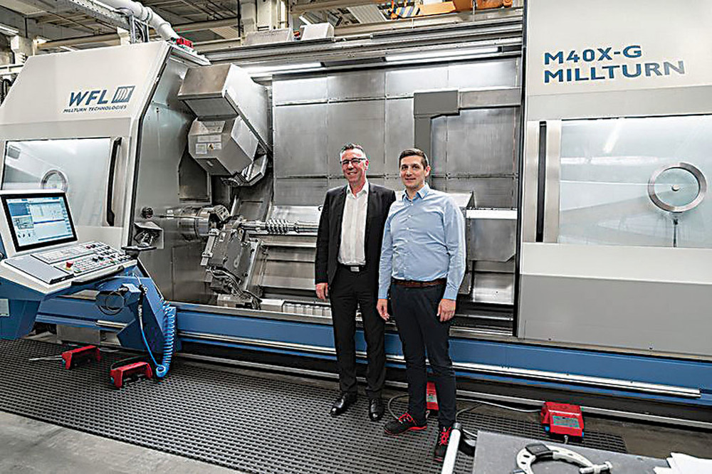 From left to right: Michael Müller (left), regional sales manager at WFL, and Marko Kost, technical support team leader at AUMA Drives, in front of the M40X-G. WFL Millturn Technologies
The product life cycle is a unique selling point at AUMA. The customer’s product idea is first taken into development, followed by the creation of a product concept before a prototype is then produced and analyzed. Once quality and production planning are completed, it is on to parts procurement.
Labeling and traceability are becoming increasingly important. It is essential in concentrated solar power, for example, because 80,000 drives are delivered to this area.
“It all works using QR codes and is traceable,” said Marko Kost, technical support team leader at AUMA Drives. “In case of a failure in the gear unit, [such as] a defective worm shaft, which is due to a material defect, you search in the corresponding material batch and know exactly which gear unit this affects, and which ones have to be replaced. This is done for all standard products in the powertrain or according to customer requirements.”
The worm shaft, worm gear and housing are the most important parts made at AUMA and are located in the powertrain. This is AUMA’s main area of expertise. The goal is a product whose performance and efficiency become a competitive advantage for the customer.
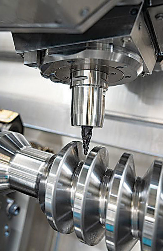 WFL designed the M40X-G mill-turn machine specifically for producing worm shafts. WFL Millturn Technologies
The machines in the AUMA Group are procured by a cross-group project team. In the case of the M40X-G mill-turn machine, it was a project team consisting of Jochen Pfeiffer, the lathe specialist coordinator and project manager from the AUMA Riester plant in Ostfildern, Germany, and Kost, as well the production management and the shift leader for turning from Coswig, and central purchasing at the AUMA Riester plant in Muellheim.
The worm shafts are produced on the WFL machine. AUMA’s high-performance worm gear units can be found in concrete mixing plants, among other applications. The previous machining process for producing worm shafts was less than ideal, according to Kost. “The process for manufacturing this shaft part used to involve a lot of individual steps: turning, clamping, pre-machining, pre-milling the gear teeth and grinding the gear teeth — an extremely expensive process. Then it was time for the heat treatment. The part has to be annealed because the milling and turning process sometimes causes the shafts to twist. “After that, it was on to the finish milling of the shafts. We would pre-grind the gear teeth and finally carry out the heat treatment and case hardening before re-clamping the shaft on the turning machine. Both sides were turned, and slots were then milled before moving the part to yet another machine for the finish grinding of the gear teeth. Finally, we carried out finish grinding the seats externally in the cylindrical grinding machine. That’s a lot of individual processes with an extremely long lead time.”
With the mill-turn machine from WFL, the worm shaft can be preturned completely in just one clamping operation. The gearing is pre-machined, which means that there is no longer any need to pregrind them. The shaft goes from the machine straight to case hardening. Once this has been completed, the rest of the machining process — right through to the finished worm shaft — continues in the M40X-G.
Other than the case hardening, finish grinding of the gear teeth is the only remaining process still carried out on another machine. All other processes are performed on the M40X-G.
The time savings are significant, Kost said. “We have reduced the setup time by 50%. The machining time has been reduced by 15 to 20%, but we can see more potential here. The lead time has been halved. We still have the external hardening process, which sometimes prevents us from being flexible. But thanks to the WFL, we can now theoretically deliver within four weeks if a super urgent order comes in.”
The machine is designed specifically for producing worm shafts, but there are plans to also machine the sleeves that are fitted in the gear unit. These sleeves provide the output drive, which the customer chooses, in the gear unit.
“For example, we can install a shaft, but the holes are often specified by the customer,” Kost said. “We have already done this with internal gears too. We are very much guided by the customer in this area. But as for the gear unit itself, the diameters and so on, we stick to the standard.”
Batch sizes range from one to 24, Kost noted. “Due to the small batch sizes, it was extremely important to us that the machine is easy to set up. That’s why we have a large tool magazine, so that we can set up parallel to machining time. In the past, we would frequently have to change the jaws due to the jaw chuck. Now, we have the same jaw chuck on the main and counter spindles. We sometimes use face drivers for special machining during the high-precision finishing process, and we can attach these face drivers to the jaw chuck so that we are under way in no time.”
The tolerance specifications are in a narrow range, in some cases down to IT6, which AUMA machines completely using the in-process measuring probe by means of turning, Kost said. “We used to always be told that we had to grind to achieve this, but actually we can get the same result by turning. That’s a massive competitive advantage for us. And, of course, the design with the slant bed, that’s critical for stability.”
The M40X-G is also equipped with a pick-up magazine for the grinding unit. This can also be used for boring bars later on and is a huge advantage, according to Kost. “We used to use parameter software to help us produce the gear teeth on the shaft. The operator entered the data, but this was a big challenge for us because you always had to draw the tooth when programming and then simulate it in the program. WFL has developed a specific programming cycle for us for this process, so we can now program the gear teeth directly at the machine.
“You simply enter the gear teeth data and then mill or turn. There is no longer any need for external programming. The whole process runs extremely smoothly. It really was a fantastic collaboration. We can also measure the gear teeth with a measuring probe and then finish them.”
AUMA uses the machine’s measuring technology to do this. The shaft’s concentric running is also measured on the machine without turning the shaft. “That’s really great, because the part can stay in the machine the whole time,” Kost said.
As for future projects, Kost said the company has some ideas: “We definitely want to make further progress with programming and simulations, as that will save us run-in time. We need to be using the machine efficiently. Also, three machines are going to be removed from the production area in Coswig thanks to the new M40X-G. There is a growing space for machines that come with automation. And everyone always needs space.”
Related Glossary Terms
- boring
boring
Enlarging a hole that already has been drilled or cored. Generally, it is an operation of truing the previously drilled hole with a single-point, lathe-type tool. Boring is essentially internal turning, in that usually a single-point cutting tool forms the internal shape. Some tools are available with two cutting edges to balance cutting forces.
- chuck
chuck
Workholding device that affixes to a mill, lathe or drill-press spindle. It holds a tool or workpiece by one end, allowing it to be rotated. May also be fitted to the machine table to hold a workpiece. Two or more adjustable jaws actually hold the tool or part. May be actuated manually, pneumatically, hydraulically or electrically. See collet.
- cylindrical grinding
cylindrical grinding
Grinding operation in which the workpiece is rotated around a fixed axis while the grinding wheel is fed into the outside surface in controlled relation to the axis of rotation. The workpiece is usually cylindrical, but it may be tapered or curvilinear in profile. See centerless grinding; grinding.
- gang cutting ( milling)
gang cutting ( milling)
Machining with several cutters mounted on a single arbor, generally for simultaneous cutting.
- grinding
grinding
Machining operation in which material is removed from the workpiece by a powered abrasive wheel, stone, belt, paste, sheet, compound, slurry, etc. Takes various forms: surface grinding (creates flat and/or squared surfaces); cylindrical grinding (for external cylindrical and tapered shapes, fillets, undercuts, etc.); centerless grinding; chamfering; thread and form grinding; tool and cutter grinding; offhand grinding; lapping and polishing (grinding with extremely fine grits to create ultrasmooth surfaces); honing; and disc grinding.
- grinding machine
grinding machine
Powers a grinding wheel or other abrasive tool for the purpose of removing metal and finishing workpieces to close tolerances. Provides smooth, square, parallel and accurate workpiece surfaces. When ultrasmooth surfaces and finishes on the order of microns are required, lapping and honing machines (precision grinders that run abrasives with extremely fine, uniform grits) are used. In its “finishing” role, the grinder is perhaps the most widely used machine tool. Various styles are available: bench and pedestal grinders for sharpening lathe bits and drills; surface grinders for producing square, parallel, smooth and accurate parts; cylindrical and centerless grinders; center-hole grinders; form grinders; facemill and endmill grinders; gear-cutting grinders; jig grinders; abrasive belt (backstand, swing-frame, belt-roll) grinders; tool and cutter grinders for sharpening and resharpening cutting tools; carbide grinders; hand-held die grinders; and abrasive cutoff saws.
- hardening
hardening
Process of increasing the surface hardness of a part. It is accomplished by heating a piece of steel to a temperature within or above its critical range and then cooling (or quenching) it rapidly. In any heat-treatment operation, the rate of heating is important. Heat flows from the exterior to the interior of steel at a definite rate. If the steel is heated too quickly, the outside becomes hotter than the inside and the desired uniform structure cannot be obtained. If a piece is irregular in shape, a slow heating rate is essential to prevent warping and cracking. The heavier the section, the longer the heating time must be to achieve uniform results. Even after the correct temperature has been reached, the piece should be held at the temperature for a sufficient period of time to permit its thickest section to attain a uniform temperature. See workhardening.
- lathe
lathe
Turning machine capable of sawing, milling, grinding, gear-cutting, drilling, reaming, boring, threading, facing, chamfering, grooving, knurling, spinning, parting, necking, taper-cutting, and cam- and eccentric-cutting, as well as step- and straight-turning. Comes in a variety of forms, ranging from manual to semiautomatic to fully automatic, with major types being engine lathes, turning and contouring lathes, turret lathes and numerical-control lathes. The engine lathe consists of a headstock and spindle, tailstock, bed, carriage (complete with apron) and cross slides. Features include gear- (speed) and feed-selector levers, toolpost, compound rest, lead screw and reversing lead screw, threading dial and rapid-traverse lever. Special lathe types include through-the-spindle, camshaft and crankshaft, brake drum and rotor, spinning and gun-barrel machines. Toolroom and bench lathes are used for precision work; the former for tool-and-die work and similar tasks, the latter for small workpieces (instruments, watches), normally without a power feed. Models are typically designated according to their “swing,” or the largest-diameter workpiece that can be rotated; bed length, or the distance between centers; and horsepower generated. See turning machine.
- milling
milling
Machining operation in which metal or other material is removed by applying power to a rotating cutter. In vertical milling, the cutting tool is mounted vertically on the spindle. In horizontal milling, the cutting tool is mounted horizontally, either directly on the spindle or on an arbor. Horizontal milling is further broken down into conventional milling, where the cutter rotates opposite the direction of feed, or “up” into the workpiece; and climb milling, where the cutter rotates in the direction of feed, or “down” into the workpiece. Milling operations include plane or surface milling, endmilling, facemilling, angle milling, form milling and profiling.
- milling machine ( mill)
milling machine ( mill)
Runs endmills and arbor-mounted milling cutters. Features include a head with a spindle that drives the cutters; a column, knee and table that provide motion in the three Cartesian axes; and a base that supports the components and houses the cutting-fluid pump and reservoir. The work is mounted on the table and fed into the rotating cutter or endmill to accomplish the milling steps; vertical milling machines also feed endmills into the work by means of a spindle-mounted quill. Models range from small manual machines to big bed-type and duplex mills. All take one of three basic forms: vertical, horizontal or convertible horizontal/vertical. Vertical machines may be knee-type (the table is mounted on a knee that can be elevated) or bed-type (the table is securely supported and only moves horizontally). In general, horizontal machines are bigger and more powerful, while vertical machines are lighter but more versatile and easier to set up and operate.
- parallel
parallel
Strip or block of precision-ground stock used to elevate a workpiece, while keeping it parallel to the worktable, to prevent cutter/table contact.
- tolerance
tolerance
Minimum and maximum amount a workpiece dimension is allowed to vary from a set standard and still be acceptable.
- turning
turning
Workpiece is held in a chuck, mounted on a face plate or secured between centers and rotated while a cutting tool, normally a single-point tool, is fed into it along its periphery or across its end or face. Takes the form of straight turning (cutting along the periphery of the workpiece); taper turning (creating a taper); step turning (turning different-size diameters on the same work); chamfering (beveling an edge or shoulder); facing (cutting on an end); turning threads (usually external but can be internal); roughing (high-volume metal removal); and finishing (final light cuts). Performed on lathes, turning centers, chucking machines, automatic screw machines and similar machines.
- turning machine
turning machine
Any machine that rotates a workpiece while feeding a cutting tool into it. See lathe.