Cutting tool nomenclatures aren’t as cryptic as they look. Those code letters and numbers can be deciphered to reveal a wealth of information about indexable inserts.
Tool users are exposed regularly to various indexable-insert nomenclature and identification codes. For people trying to find the right tool for their job, these identification systems can be a confusing assortment of letters and numbers. And with the increasing use of superabrasive (diamond, PCD, and PCBN) cutting tools, the tool nomenclatures have evolved still further. Polycrystalline cutting tools often have unique identifying codes that are supplier-dependent. These only add to the size and scope of an already extensive string of identification code letters and numbers.
Most of the world’s insert manufacturers use either the American National Standards Institute (ANSI) indexable-insert identification system or the International Organization of Standards (ISO) system. The ANSI system is confined mainly to the United States and is available as ANSI publication No. 212.4. Most of the rest of the world uses the ISO identification system, although it is used in the United States as well. Some European and Asian cutting tool suppliers use ISO codes in their U.S. sales efforts, and U.S. tool exporters often code their products in ISO standard for overseas sales and distribution. This global distribution of cutting tools makes it important to understand both systems. The ANSI and ISO codes are illustrated on pages 36 and 37, respectively.
ANSI System
The ANSI code system (Figure 1) has been generally adopted by the U.S. cutting tool industry for the quick and accurate identification of indexable inserts. This system has been widely used throughout the United States for many years. The code system has evolved with the advancement of insert design and technology. But the code hasn’t evolved to the point where it encompasses all advancements. As shown in Figure 1, tool producers have added custom prefixes and suffixes to the standard code where needed.
The current ANSI code consists of up to 10 alphanumeric characters. Of these 10, the first seven are most commonly used. The first four of these seven characters are letters that identify the geometric characteristics of the cutting tool. The next three characters are numbers that describe the size of the cutting tool.
Specifically, the first character identifies the shape of the cutting tool. There are standard designations for simple shapes such as round (R), triangular (T), and square (S), as well as for more complex shapes such as diamonds (C, D, M, and V), octagons (O), pentagons (P), and parallelograms (A, B, E, and F). Although an extensive range of tool shapes is covered in the standard code, many manufacturers produce special shapes for which they adopt their own code identification. For example, one manufacturer may use the code G to designate a 45° parallelogram insert. This is not a universally accepted designation, however; another manufacturer may use G to signify an uneven hexagon with three flat sides and three sides ground in an arc. These special codes can sometimes cause confusion, but a code system that covers all possibilities is impractical. There are simply too many potential insert geometries.
 T _ _ _ - _ _ _ - _ - _ _
The second character identifies the clearance angle of the cutting tool, which is the angle formed between the top of the tool and the flank surface. The angle specified is the angular difference from 90°. For example, the code letter N represents a 90° relationship between top and flank, or 0° clearance. This is commonly called a negative-clearance-angle cutting tool. Another popular tool has the code letter P. This represents a positive clearance angle of 11°. The most common clearance angles range from 0° (N) to 30° (G).
T N _ _ - _ _ _ - _ - _ _
The third character identifies the combination of tolerance ranges under which the cutting tool is manufactured. Tool users frequently will see the letter G in this position. This represents a tolerance of 0.001" on the tool’s inscribed circle (IC) dimension, 0.001" on the tip-radius altitude, and 0.005" on the tool thickness. The M tolerance code is also very popular for nonground, roughing-style tools. This code represents a tolerance of 0.002" to 0.010" on the tool’s IC and 0.005" on the tool thickness. The tolerance chart in Figure 1 describes a range of indexable-insert tolerances.
T N M _ - _ _ _ - _ - _ _
The fourth character describes the physical characteristics of the cutting tool’s mounting system and cutting-surface configuration. For instance, a flat-top, clamp-type cutting tool would have the code N. If that same flat-top cutting tool had a center hole for screw mounting, it would have the code A. If its center hole was countersunk on one side, it would have the code B. If the hole had an additional countersink on the opposite side, the insert would have the code C.
A different letter will be used in the fourth position if the insert has a clamp-on or molded-in chipbreaker. For example, if an N-type tool had a chip groove on one top surface, it would be called an R-style insert. If it had chip grooves on top and bottom, it would be an F-style tool. Add a hole, and it would be an M-type (one-sided) or G-type (two-sided) tool.
The fourth character describes many tool features. Currently, there are more than 17 different tool configurations described in the standards. And if this is not enough for the tool producer, there is the X designation for special designs. With all these possibilities, it is curious to note that this character is often omitted when describing commonly known turning inserts or when describing milling inserts.
T N M G - _ _ _ - _ - _ _
At this point, the code system changes from letters to numbers. The next three characters describe the physical size of the cutting tool.
The first of the numbers, or the fifth character in the code system, represents the insert’s IC in 1/8" increments. For example, a 1/4" IC insert is described by the number 2, representing 2/8". It follows that a 1/2" IC insert is represented by the number 4 and a 1" IC insert is represented by the number 8. The exception to this rule applies to small inserts with IC dimensions under 1/4". For small tools, the number in this place represents the IC dimension in 1/32" increments. The number 2 represents 2/32" or 1/16". It follows that 3 would describe 3/32" and so on, up to a 1/4" IC tool.
T N M G - 4 _ _ - _ - _ _
The sixth character represents the thickness of the cutting tool. Again, there is a split between large and small inserts. For inserts with IC dimensions of 1/4" and greater, this number describes the thickness in 1/16" increments. For small tools with IC dimensions less than 1/4", this number represents the thickness in 1/32" increments. A popular triangular small tool has a thickness of 3/32", which would be represented by the number 3 in the sixth place.
T N M G - 4 3 _ - _ - _ _
The seventh character can be a number or a letter. Numbers are used for tools with corner radii, which are normally inserts used in turning operations. The number describes the size of the corner radius in 1/64" increments. For example, a 1/32" radius is represented by the number 2, a 3/64" radius by the number 3.
T N M G - 4 3 2 - _ - _ _
Milling tools differ from turning tools in that they use a letter in the seventh place to describe the design of corner chamfers on the tool. Like the fourth place, this can be a very confusing part of the insert code. The seventh character describes the angle of the corner chamfers, relative to the insert side. The insert hand, left or right, is also a factor in the code letter used, as well as the presence of one or two chamfers per corner. For example, the letter E represents a 15° chamfer on a right-hand tool. The same tool in left-hand configuration would have the letter H in the seventh place. If the tool had two 15° chamfers, the code letter would be L. Because there are so many possible combinations, it’s best to reference a tool supplier’s identification guide when specifying a tool on an order using this character.
S N K _ - 4 3 E - _ - _ _
The eighth character also can be a letter or a number. When describing a nonmilling insert, which will be identified with a number in the seventh place, the eighth character is a letter. This character describes additional characteristics of the tools. An A, B, or C specifies honed edges, an N indicates negative lands, and a J identifies polished insert-rake surfaces.
T N M G - 4 3 2 - C - _ _
Milling insert tools, which have a letter in the seventh place in their identifying code, use a number in the eighth place. This number represents a milling insert’s wiper flat length and is measured in 1/32" increments. The wiper flat is most often a chamfer and ultimately produces the surface finish on the workpiece.
S N K _ - 4 3 E - 2 - _ _
For nonmilling inserts, the ninth and tenth places are most often used by tool producers to distinguish special features of their products. But for milling inserts, the ninth character indicates the direction of cut. This place is identified by the letter R for right or L for left. For both milling and turning tools, the tenth character is used at the cutting tool producer’s option.
S N K _ - 4 3 E - 2 - R _
ISO System
While the ISO cutting tool description system (Figure 2) uses metric units rather than inches, it has many of the features of the ANSI system. In particular, the first four characters are practically identical to the ANSI system. The first is the shape, the second is the clearance angle, the third is the tolerance range, and the fourth is the cutting-surface configuration and mounting system. A notable exception: In the ISO system, the fourth character is always used when describing milling inserts; in the ANSI system, it is often omitted.
T N M A - __ __ __ - __ - __
The big difference first shows itself in the fifth place. In the ISO system, the fifth place describes the cutting tool size by specifying the tool’s side length to the closest millimeter. This place therefore requires two digits for a proper description. Tool sizes designated under this system will vary significantly from tool sizes under the ANSI system, as the following example illustrates.
In the ANSI system, a 1/2" IC insert is represented by the number 4 (4/8"), regardless of the tool’s shape. But because a tool’s shape affects its side length, its shape will also affect its size description. Under the ISO system, a 1/2" IC insert will be represented by the number 12 (12mm) if it is a round, square, or 80° diamond insert; 22 if it is triangular; or 15 if it is a 55° diamond tool.
T N M A - 16 __ __ - __ - __
The sixth place in the code is also different from the ANSI system. Like the fifth place, it requires two digits and describes the tool thickness rounded off to the lowest whole millimeter. For example, a 1/8" thick cutting tool measures 3.18mm and has the code 03. A 3/16" thick cutting tool measures 4.76mm and has the code 04.
T N M A - 16 03 __ - __ - __
As in the ANSI code, the seventh character in the ISO code can be a number or a letter. Numbers are used for tools having corner radii, or turning tools, and letters are used for milling tools. For turning tools, the seventh place represents the nose radius size on the cutting tool. Once again, the ISO system uses a two-digit code in this place. The code represents the radius size in tenths of a millimeter. For example, a 1mm nose radius would have the code 10, whereas a 0.5mm radius would have the code 05.
T N M A - 16 03 08 - __ - __
For milling tools, the ISO system breaks the two letters in the seventh place into separate tool identifiers. The first letter identifies the angle of the wiper flat, or actual cutting edge, relative to the insert side, much like the ANSI code. The second letter describes the clearance angle of the wiper flat.
This tool geometry feature is not part of the ANSI system. In the example below, the letter A describes corner chamfers at 45° to the tool sides. The N following the A means the surface has a 0° or negative clearance angle.
T N L N - 12 04 AN - __ - __
As in the ANSI system, there are additional characters in the ISO system that can be employed but are often omitted. They are the cutting edge condition, the direction of feed, and the manufacturer’s optional area.
Superabrasive Inserts
Superabrasive cutting tools can be supplied in a wide variety of shapes and sizes. Three groups or categories can be established: full-topped indexable inserts, tipped indexable and single-edge cutting tools, and special-design tools such as rotating tools and saws.
Full-topped indexable inserts, tools with a superabrasive layer covering the entire top or top and bottom surfaces, can be identified adequately with the code systems just described. This is not so with tipped inserts, which have a substrate material that is formed into the familiar shapes described by ANSI or ISO codes. The actual cutting material, the superabrasive segment, is formed into an almost infinite variety of shapes and sizes and is inlaid into the base material.
On a tipped cutting tool, the size of the superabrasive insert, or segment, is a variable. Depending on the end user’s planned DOC, he might utilize a very small or very large segment.
At this time, each superabrasive cutting tool supplier has its own unique method of coding tipped inserts. Some are close to the ANSI or ISO standard, while others use codes that cannot be related to the insert standards. The tool suppliers that stay close to the ANSI standard often will add a suffix to the normally used seven-character identification code. This suffix is used to describe the superabrasive segment’s working edge length. In some instances, it also identifies the grade of the superabrasive material. For example, one supplier may use the suffixes 2F and 2G for diamond-tipped inserts and 4F and 4G for PCBN-tipped tools. Other suppliers may use two numbers to represent the length of the segment as measured down the insert side length. Still others may not list the side length at all, and thus only use the standard ANSI code as though the segment were not even on the tool.
A standard code system for tipped inserts is being reviewed by ANSI. The code combination is based on a suffix being added to the normal 10-character ANSI system. This suffix describes the details of the segment geometry. It is hoped that superabrasive tool producers will adopt the proposed suffix standard as they have adopted the existing code. It is certain that the indexable-insert code systems will continue to evolve. With new cutting tool geometries and materials being developed, the need to have a standardized description will remain. To stay current, users should periodically review the cutting tool identification information from their suppliers.
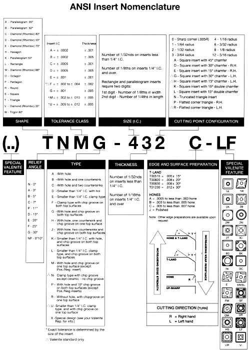
Figure 1: ANSI insert nomenclature. Provided by Valenite Inc.
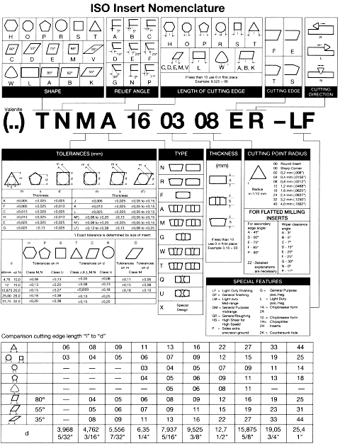
Figure 2: ISO insert nomenclature. Provided by Valenite Inc.
About the Author
Richard Thalmann is general manager of superabrasive products for Wendt Grinding Corp., Rochester Hills, MI.
Related Glossary Terms
- chipbreaker
chipbreaker
Groove or other tool geometry that breaks chips into small fragments as they come off the workpiece. Designed to prevent chips from becoming so long that they are difficult to control, catch in turning parts and cause safety problems.
- clearance
clearance
Space provided behind a tool’s land or relief to prevent rubbing and subsequent premature deterioration of the tool. See land; relief.
- countersink
countersink
Tool that cuts a sloped depression at the top of a hole to permit a screw head or other object to rest flush with the surface of the workpiece.
- feed
feed
Rate of change of position of the tool as a whole, relative to the workpiece while cutting.
- flat ( screw flat)
flat ( screw flat)
Flat surface machined into the shank of a cutting tool for enhanced holding of the tool.
- gang cutting ( milling)
gang cutting ( milling)
Machining with several cutters mounted on a single arbor, generally for simultaneous cutting.
- grinding
grinding
Machining operation in which material is removed from the workpiece by a powered abrasive wheel, stone, belt, paste, sheet, compound, slurry, etc. Takes various forms: surface grinding (creates flat and/or squared surfaces); cylindrical grinding (for external cylindrical and tapered shapes, fillets, undercuts, etc.); centerless grinding; chamfering; thread and form grinding; tool and cutter grinding; offhand grinding; lapping and polishing (grinding with extremely fine grits to create ultrasmooth surfaces); honing; and disc grinding.
- inscribed circle ( IC)
inscribed circle ( IC)
Imaginary circle that touches all sides of an insert. Used to establish size. Measurements are in fractions of an inch and describe the diameter of the circle.
- inscribed circle ( IC)2
inscribed circle ( IC)
Imaginary circle that touches all sides of an insert. Used to establish size. Measurements are in fractions of an inch and describe the diameter of the circle.
- milling
milling
Machining operation in which metal or other material is removed by applying power to a rotating cutter. In vertical milling, the cutting tool is mounted vertically on the spindle. In horizontal milling, the cutting tool is mounted horizontally, either directly on the spindle or on an arbor. Horizontal milling is further broken down into conventional milling, where the cutter rotates opposite the direction of feed, or “up” into the workpiece; and climb milling, where the cutter rotates in the direction of feed, or “down” into the workpiece. Milling operations include plane or surface milling, endmilling, facemilling, angle milling, form milling and profiling.
- polycrystalline diamond ( PCD)
polycrystalline diamond ( PCD)
Cutting tool material consisting of natural or synthetic diamond crystals bonded together under high pressure at elevated temperatures. PCD is available as a tip brazed to a carbide insert carrier. Used for machining nonferrous alloys and nonmetallic materials at high cutting speeds.
- tolerance
tolerance
Minimum and maximum amount a workpiece dimension is allowed to vary from a set standard and still be acceptable.
- turning
turning
Workpiece is held in a chuck, mounted on a face plate or secured between centers and rotated while a cutting tool, normally a single-point tool, is fed into it along its periphery or across its end or face. Takes the form of straight turning (cutting along the periphery of the workpiece); taper turning (creating a taper); step turning (turning different-size diameters on the same work); chamfering (beveling an edge or shoulder); facing (cutting on an end); turning threads (usually external but can be internal); roughing (high-volume metal removal); and finishing (final light cuts). Performed on lathes, turning centers, chucking machines, automatic screw machines and similar machines.
- wiper
wiper
Metal-removing edge on the face of a cutter that travels in a plane perpendicular to the axis. It is the edge that sweeps the machined surface. The flat should be as wide as the feed per revolution of the cutter. This allows any given insert to wipe the entire workpiece surface and impart a fine surface finish at a high feed rate.