VISI 2020.0 CAD/CAM Software
VISI 2020.0 CAD/CAM Software
The latest release of VISI CAD/CAM, from Hexagon Manufacturing Intelligence's Production Software business, improves mold and progressive-die design processes, along with enhancement to the Reverse module, specifically designed for the mold and die market.
The latest release of VISI CAD/CAM, from Hexagon Manufacturing Intelligence's Production Software business, improves mold and progressive-die design processes, along with enhancement to the Reverse module, specifically designed for the mold and die market.
New part-unfolding technology has been introduced in VISI 2020.0, giving the ability to work directly on the original solid part without needing to extract the model's skin.
Sheet-metal part recognition now provides an improved graphical representation of the part analyzed by identifying bends, planar faces and features.
VISI Product Manager Marco Cafasso says the advantage of the new technology is its associativity with the original model during the die design process, as it allows the original part to be edited and changes to be made automatically on the study of the part. "It also means the blank calculation will completely unfold all the detected features and coining faces. The step-by-step process unfolds just the features across the selected bend by automatically rebuilding the relative solid model, and the coining faces will be rebuilt on each step."
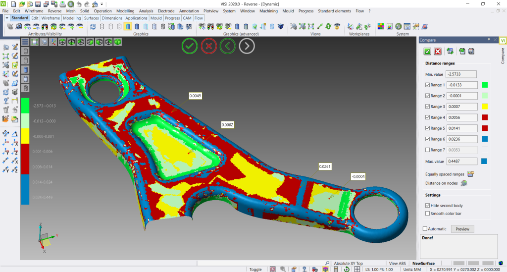
Enhancements to the Reverse module provide new functionalities for both Reverse and Casting processes, giving greater flexibility for both processes. Features such as clipping plane management for point scanning, planar face and draft analysis on mesh data, adapting a mesh to a boundary, and best fit, improve the reverse process from point scanning to solid model generation, and manufacturing.
A new Compare feature lets the user compare two entities, such as a point cloud, mesh, or solid, by checking the relative distance; the graphical results show different colors in reference to the distance ranges. The system also shows the relative distance between the two selected entities during the comparison by simply selecting a point. "The Best Fit and Compare functions are essential for both the Reverse, Casting and manufacturing processes," Cafasso says.
Additional Meusburger Mold Tool templates (FB, FM and FW types) are now incorporated, including new plates, as well as standard components. The new mold templates also include assemblies from the same supplier. The benefits of this are that the mold designer will be able to call on Meusburger's latest mold assemblies.
VISI's Flow Analysis has been improved by new mesh group technology specifically designed for FEM analysis. It gives a high quality mesh while reducing computation time by providing new options to adapt and fit the mesh accordingly to the model's shape. "It's possible to control the mesh orientation, the curvature of the model, and smooth the mesh on the transition area, leading to a higher quality, accurate Flow Analysis process," Cafasso says.
The flow lines in VISI 2020.0 can now be shown, highlighting possible 'hesitations' of the filling from isochrones. "This is especially important, as hesitation occurs when the melt flow slows down or stops along a particular flow path, leading to possible asymmetrical and unpredictable flow patterns," Cafasso says. Such hesitation can reduce part quality, caused by variations in surface appearance, poor packing, high stresses, and non-uniform orientation of the plastic molecules. "If the flow front freezes completely, part of the cavity may remain unfilled, resulting in a short tool," Cafasso says.
However, engineers can now graphically identify possible quality issues caused by flow hesitations, and then simulate alternative solutions.
With thermal analysis becoming increasingly more important in optimizing mold cooling, the Flow Thermal function has been enhanced with improved coolant flow-rate suggestions, giving an indicative value for a single cooling circuit and an improved solid mesh definition for the mold cavity block, along with each axis, to offer more accurate results.
Thanks to a new direct interface between VISI and Digimat, data showing material local rigidity can be exported into Digimat for the structural FEM analysis process. MSC Software's Digimat positions itself between the manufacturing and structural analysis by allowing chosen composite materials to be added to a new reference model to simulate and predict the molded part's mechanical properties.
By bridging the independent Flow injection molding and structural analysis environments such as MARC, APEX and ANSYS, Digimat provides added value with a more realistic stress analysis simulation. Extra data has been added to the material database to better match fiber characteristics, including information such as shape and length of the filler.
Overall benefits include:
- Realistic structural analysis simulation
- Influencing design construction to improve the molded part's mechanical behavior
- Optimizes material selection and fiber properties to improve mechanical resistance
- Validate the part's properties in reference to the mold design.