Dear Doc: Our cylindrical grinding machine has the option of varying the workpiece rpm. Is this legit? How does it work?
The Doc replies: Yes, it’s definitely legit. Here are the two main reasons it’s helpful.
Reason 1: When you begin to grind, the wheel/spindle assembly bounces up and down – ever so slightly – at its natural frequency. This can lead to self-excited workpiece- regenerative chatter. As the workpiece rotates, the slightly bouncing wheel creates small lobes on the workpiece. As these lobes come around again, they create force pulsations that excite the wheel/spindle, causing it to bounce slightly more, which creates bigger lobes. These bigger lobes come around again and excite the wheel/ spindle even more, causing higher bouncing, which creates bigger lobes, which come around again and excite the wheel/spindle even more, which creates even bigger lobes. Next thing you know, the wheel/spindle is bouncing like crazy – i.e., chatter is out of control.
For the lobes to excite the bouncing of the wheel/spindle, the wheel/ spindle bouncing and the workpiece lobes have to be in-sync, with no phase shift between the two.
This depends on the ratio of wheel/ spindle natural frequency and workpiece rpm. If the bouncing/lobes are in-sync, chatter gets worse. If the bouncing/lobes are out-of-sync, chatter is attenuated – i.e., it dies down.
Sometimes bouncing/lobes are in-sync, sometimes they’re not. There’s no good way to predict when that happens. It happens mostly by chance.
If you vary the workpiece rpm, the bouncing/lobes are going in-sync and out-of-sync. Chatter may build up for a second or two, but then a second or two later it is being attenuated.
The result? Chatter doesn’t self-excite drastically.
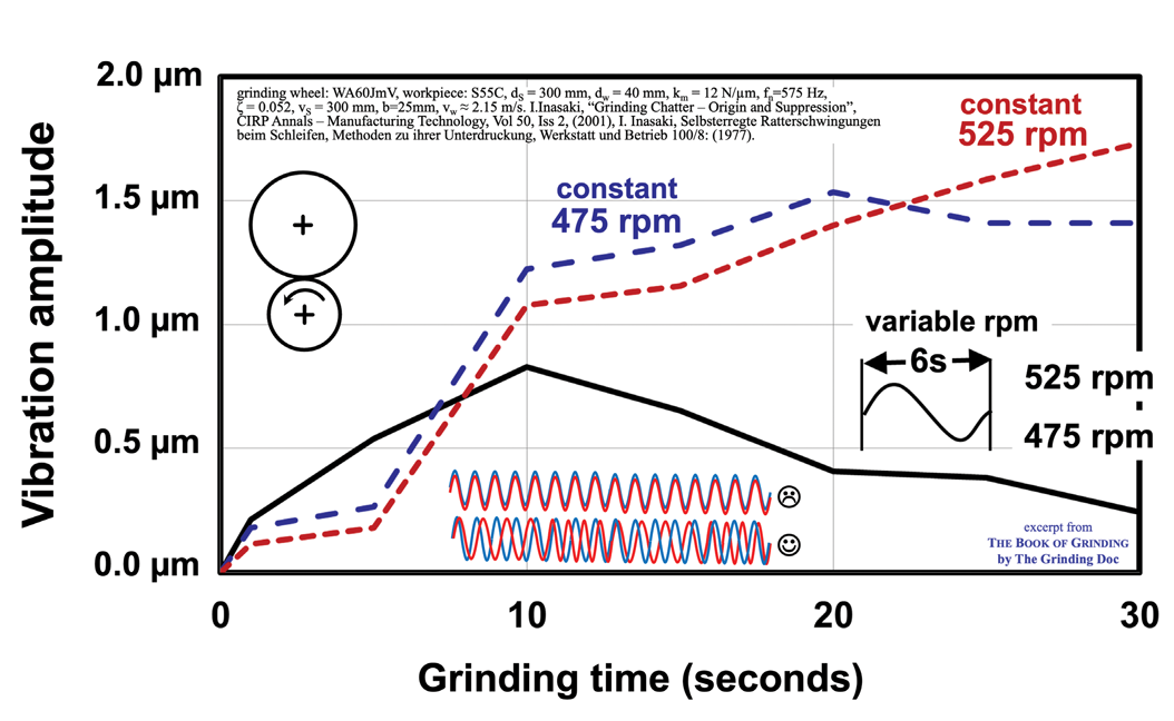 Varying the workpiece rpm causes the lobes to shift in and out of sync, which naturally builds and then dampens chatter. As shown in the figure, a ±5% rpm variation every six seconds effectively prevents chatter from escalating.
The figure shows an example of the theory proven out by measurements. A workpiece rpm variation of ±5% every six seconds was enough to keep chatter from getting out of control.
Reason 2: No wheel is perfectly balanced, and no wheel is perfectly true. Even a wheel with auto-balancing is out of balance. It’s just less out of balance.
Out-of-balance creates lobes on the workpiece. That’s fine and normal and unavoidable. That’s why we spark out, to obliterate those lobes.
But what happens when the ratio of wheel-rpm to workpiece-rpm is close to an “integer value” of 8.0000 or 9.013 or 8.9924? As we spark out, the same point on the wheel hits the same point on the workpiece, and we never obliterate those lobes. That’s why we want a ratio like 9.36488 or 8.916742. During my grinding courses, I have attendees chant the Grinder’s Mantra: “Round number bad, strange number good.”
There’s a remedy for avoiding those bad round numbers: Vary the workpiece rpm. That way, you’re never in a round number for more than a split second. You’re obliterating those lobes. The result? A round workpiece.
Related Glossary Terms
- chatter
chatter
Condition of vibration involving the machine, workpiece and cutting tool. Once this condition arises, it is often self-sustaining until the problem is corrected. Chatter can be identified when lines or grooves appear at regular intervals in the workpiece. These lines or grooves are caused by the teeth of the cutter as they vibrate in and out of the workpiece and their spacing depends on the frequency of vibration.
- cylindrical grinding
cylindrical grinding
Grinding operation in which the workpiece is rotated around a fixed axis while the grinding wheel is fed into the outside surface in controlled relation to the axis of rotation. The workpiece is usually cylindrical, but it may be tapered or curvilinear in profile. See centerless grinding; grinding.
- grinding
grinding
Machining operation in which material is removed from the workpiece by a powered abrasive wheel, stone, belt, paste, sheet, compound, slurry, etc. Takes various forms: surface grinding (creates flat and/or squared surfaces); cylindrical grinding (for external cylindrical and tapered shapes, fillets, undercuts, etc.); centerless grinding; chamfering; thread and form grinding; tool and cutter grinding; offhand grinding; lapping and polishing (grinding with extremely fine grits to create ultrasmooth surfaces); honing; and disc grinding.
- grinding machine
grinding machine
Powers a grinding wheel or other abrasive tool for the purpose of removing metal and finishing workpieces to close tolerances. Provides smooth, square, parallel and accurate workpiece surfaces. When ultrasmooth surfaces and finishes on the order of microns are required, lapping and honing machines (precision grinders that run abrasives with extremely fine, uniform grits) are used. In its “finishing” role, the grinder is perhaps the most widely used machine tool. Various styles are available: bench and pedestal grinders for sharpening lathe bits and drills; surface grinders for producing square, parallel, smooth and accurate parts; cylindrical and centerless grinders; center-hole grinders; form grinders; facemill and endmill grinders; gear-cutting grinders; jig grinders; abrasive belt (backstand, swing-frame, belt-roll) grinders; tool and cutter grinders for sharpening and resharpening cutting tools; carbide grinders; hand-held die grinders; and abrasive cutoff saws.