While it’s nearly impossible to quantify the most common challenges or most important considerations when turning, experts agree that the five aspects of turning discussed below should be considered.
It’s important to note that each factor has the potential to impact the others. So, instead of looking at each issue individually, it’s recommended machinists take a holistic best-practices approach to turning.

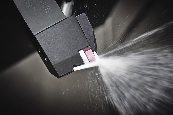
Application of coolant directly to the cutting edge is important for heat management, chip evacuation and surface finish. Image courtesy Seco Tools.
1. Heat Management
“You absolutely have to figure out a way to disperse heat,” said Scott Leitch, sales and marketing manager at Exsys Tool Inc., San Antonio, Fla. “If the toolholder doesn’t have coolant either running through it or running on top of the assembly while it’s in operation, heat will build up and can have negative effects on tool life, surface finish and part quality.” Leitch added that sealed toolholders (for the application of through-tool coolant) help the coolant disperse heat more efficiently.
Kurt Ludeking, product manager at Walter USA LLC, Waukesha, Wis., noted most machines are supplied with coolant ports and, in theory, operators just need to direct the coolant to the cutting edge for proper heat
removal.
“That works … sometimes,” he said. “It depends on a lot of things, and the coolant flow can get misaligned during routine maintenance, or even knocked out of the way by chips flying around. If you don’t have the coolant directed properly, it won’t be effective and you’ll wind up getting a lot of crater wear and flank wear.”
High-pressure through-coolant is typically regarded as the best solution, but it’s not always an option, such as when clearances don’t allow for a bulky high-pressure apparatus, or when the part is too thin or delicate to withstand the pressure.
Absent high-pressure coolant, using toolholders that direct the coolant through the toolholder and straight to the cutting edge helps, Ludeking said. “Even if it’s relatively low pressure, around 150 psi or so, which is pretty typical for most modern machines, you get a better cooling effect, because it’s always directed right at the cutting edge.”
However, while heat management is certainly important, not everyone agrees it’s a major concern.
Don Graham, turning product manager at Seco Tools LLC, Troy, Mich., said the real issue is tool life, and, while heat management certainly plays a role, its impact has been drastically diminished by modern tool geometries and
coatings.
“Tool life relates to heat management, but with modern tools from any good cutting tool company, heat shouldn’t be a problem,” he said. “I fear that people who worry about heat management are probably just not using the right tools at the right speeds and feeds.”
2. Setup Selection
Rather than focusing on heat management, Graham recommends operators optimize tool and toolholder selection—although he admits that can be easier said than done.
“I don’t think any cutting tool company, including Seco, has an easy way to select the ‘best’ cutting tool for a job,” he laughed. “When it comes to getting the tool that’s appropriate for the design of the part, there are around eight to 10 common insert shapes, each of which can be held in a number of different orientations. So, first of all, you need to determine the right insert shape, then figure out how to orient it for the job, then figure out what the proper feed, speed and grade would be for the material you’re working with. It’s all application-specific, but if you get it right, you should have very few issues to address.”
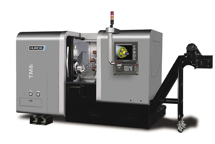
Hurco’s TMi series CNC lathes are for universal turning applications and offer an uncomplicated transition from manual numerically controlled turning, according to the company. Image courtesy Hurco North America.
Milton Ramirez, product technical specialist for CNC lathes at Haas Automation Inc., Oxnard, Calif., pointed out the importance of workholding and noted, especially when turning, a steady rest may be a necessary setup element.
“Workholding is always critical,” he said. “Whenever possible, use collets because they offer more gripping surface and, therefore, more rigidity. The next-best option is to machine jaws to the material or part size so the gripping diameters match the part and jaws.”
He also recommends a tailstock for support, if the part allows it, and noted the best type of support for long and difficult turning is a follow rest. However, this type of rest is only available on twin-turret machines, wherein the part is machined by one turret and supported by the other.
For lathes with only one turret, he explained, the most common workholders are steady rests, which have a body that does not move. “Only the grippers are programmable for gripping or releasing the part.”
Once the tool and the part are held in place, said Michael Cope, product technical specialist at Indianapolis-based machine tool builder Hurco North America, the next essential step is choosing the proper insert geometry.
“Insert selection can sometimes go beyond the typical decision between corner radius and the grade of a particular insert,” he noted. “For more-complex operations than simple facing and shoulder turning, picking the right insert geometry is a key component. Increasing the lead angle of the cutter can also help. Higher lead angles and positive-raked inserts produce a better surface finish than tools with a shallower cutting angle.”
3. Surface Finish
In any machining operation, part quality is of paramount importance, and surface finish is a major component. Besides higher lead angles and positive-raked inserts, how can machinists impart the best surface finish from their turning operation? Use wiper inserts, according to Walter’s Ludeking. They are designed to leave the surface with half the roughness of a standard turning insert run at the same feed rate.
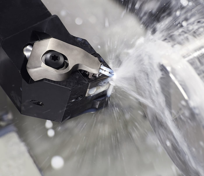
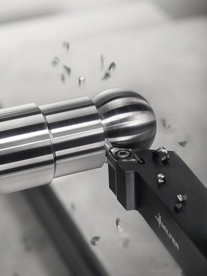
Precision coolant toolholders provide coolant as close and horizontal as possible to the effective working area under the chip, benefitting chip control and tool life and increasing speed. Image courtesy Walter USA.
“Used properly, wiper inserts can make a huge difference in surface finish,” he said. “The downside is they tend to create a lot of tool pressure, so you might have problems with deflection or chatter, especially with a thin part.” Ludeking added that extra care should be exercised when making profiling cuts, because wiper inserts are designed for straight cuts, meaning they don’t have a true radius. “The radii won’t be exactly what you’re programming in, which is something to be aware of.”
But what about when a wiper insert isn’t an option? Seco’s Graham offered an unconventional approach—spin the part faster.
“This is contrary to popular thinking, but I believe that the faster you can spin a part, the more stable it becomes,” he said. “Historically, people have been taught the opposite, and I believe that’s because of the difficulty in getting parts centered, getting them held properly, and the slower you go, the more forgiving the operation will be to those infinitesimal imbalances.”
Graham cited the gyroscopic effect as his reasoning, likening it to riding a bike: While someone riding a bicycle at 1 mph will struggle to stay upright, a motorcycle doing 100 mph can take a curve while being almost parallel to the ground, then right itself easily. “If the part that you’re machining is balanced, you get the same effect,” he said.
4. Chatter
Unlike most of the other challenges discussed here, chatter is almost completely avoidable.
“Chatter is usually caused by [using] incorrect speeds and feeds or because of lack of rigidity in the part or in the tooling, resulting in increased harmonics and vibration,” explained Hurco’s Cope. “Once chatter starts to occur, it is almost impossible to stop. Therefore, we want to stop it before it starts.” Increased feed rates and a larger tool-nose radius can help, he continued, as large tool-nose radii can accommodate higher feed rates and still impart the desired smooth surface finish.
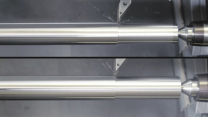
Chatter can lead to an uneven surface finish (top); a proper setup can eliminate chatter, resulting in a fine surface finish (bottom). Image courtesy Haas Automation.
Graham said anything that causes deflection will cause chatter. Cutting with a dull edge, either through improper initial selection or one that has been worn down, a lack of proper support for the tool or toolholder, cutting a springy material such as titanium without the proper geometry, built-up edge resulting from poor chip control and heat management—all of these can cause chatter. So what’s the
solution?
“It’s easy to say ‘fix the setup,’ but in practice, it’s more difficult to do,” Graham said. “We tell people to try and get as rigid of support as possible, to get the lowest overhang on the part that’s being machined, the lowest overhang on the toolholder and use a steady rest if possible. If you’re doing a shaft, you can use two toolholders at opposing ends for additional stability, if your machine has a second turret. You can use a tool above and below the shaft so the opposing radial forces balance each other. Sharper cutting edges also minimize tool pressure.
“I am a fan of running jobs as fast as they can be run, and tools today, readily available from many major manufacturers, are capable of higher speeds than tools in the past,” he continued. “Many people aren’t taking advantage of that. Seco’s Duratomic insert line is capable of machining many steels at 2,000 sfm or faster, but in my experience it is rare to see anyone turning at more than 1,000 sfm. That’s like buying a Ferrari but treating it like a Ford Taurus.”
5. Chip Control, Evacuation
Cutting will result in chips, and where there are chips, there is a need to evacuate them from the cut. Chip control is an especially challenging issue when turning, explained Walter’s Ludeking, because the tool is continuously in the cut. The result is that a turned chip has no natural breaking-off point as do other operations, such as milling. As a result, the chip must be curled upward and broken by a chipbreaker, but this introduces additional heat to the operation.
Walter’s MP4 geometry is for chip control in a variety of feed and DOC conditions, according to the company. Image courtesy Walter USA.
“The more aggressive the chipbreaker, especially in harder materials, the more heat you generate,” he said, “which brings us back around to the need for proper coolant application. There are lots of different turning insert geometries for chip control, but it’s always going to be a trade-off because of that extra heat.”
Chipbreaker geometries work in conjunction with the applied feed rate to control chip formation. Tighter chipbreaker geometries enable lighter feed rates, but if the feed rate is too low, the chips might be long and stringy (not self-breaking), or if the feed rate is too high, they might weld to the cutting edge.
Chip evacuation—removing chips from the cutting zone—also ties into surface finish, noted Hurco’s Cope. If the chips are making contact with the workpiece during the machining process, or if chips are being recut, odds are the surface finish will be negatively impacted.
“Controlling chips in a turning operation differs from other operations, because the chips often get wrapped around the spinning workpiece itself,” he said. “In milling operations, for example, you can simply keep coolant or air aimed toward the tip of the tool and prevent any chips that might be lying on the surface of the workpiece from making contact with the cutter by directing them out of the way.
“With turning, using the correct insert to break the chip, to prevent the long stringy chips from forming, becomes very important.”

Contributors
Exsys Tool Inc.
(800) 397-9748
www.exsys-tool.com
Haas Automation Inc.
(800) 331-6746
www.haascnc.com
Hurco North America
(800) 634-2416
www.hurco.com
Seco Tools LLC
(248) 528-5200
www.secotools.com/us
Walter USA LLC
(800) 945-5554
www.walter-tools.com
Contact Details

Contact Details

Contact Details
Contact Details
Contact Details

Related Glossary Terms
- built-up edge ( BUE)
built-up edge ( BUE)
1. Permanently damaging a metal by heating to cause either incipient melting or intergranular oxidation. 2. In grinding, getting the workpiece hot enough to cause discoloration or to change the microstructure by tempering or hardening.
- chatter
chatter
Condition of vibration involving the machine, workpiece and cutting tool. Once this condition arises, it is often self-sustaining until the problem is corrected. Chatter can be identified when lines or grooves appear at regular intervals in the workpiece. These lines or grooves are caused by the teeth of the cutter as they vibrate in and out of the workpiece and their spacing depends on the frequency of vibration.
- chipbreaker
chipbreaker
Groove or other tool geometry that breaks chips into small fragments as they come off the workpiece. Designed to prevent chips from becoming so long that they are difficult to control, catch in turning parts and cause safety problems.
- computer numerical control ( CNC)
computer numerical control ( CNC)
Microprocessor-based controller dedicated to a machine tool that permits the creation or modification of parts. Programmed numerical control activates the machine’s servos and spindle drives and controls the various machining operations. See DNC, direct numerical control; NC, numerical control.
- coolant
coolant
Fluid that reduces temperature buildup at the tool/workpiece interface during machining. Normally takes the form of a liquid such as soluble or chemical mixtures (semisynthetic, synthetic) but can be pressurized air or other gas. Because of water’s ability to absorb great quantities of heat, it is widely used as a coolant and vehicle for various cutting compounds, with the water-to-compound ratio varying with the machining task. See cutting fluid; semisynthetic cutting fluid; soluble-oil cutting fluid; synthetic cutting fluid.
- feed
feed
Rate of change of position of the tool as a whole, relative to the workpiece while cutting.
- flank wear
flank wear
Reduction in clearance on the tool’s flank caused by contact with the workpiece. Ultimately causes tool failure.
- gang cutting ( milling)
gang cutting ( milling)
Machining with several cutters mounted on a single arbor, generally for simultaneous cutting.
- lead angle
lead angle
Angle between the side-cutting edge and the projected side of the tool shank or holder, which leads the cutting tool into the workpiece.
- milling
milling
Machining operation in which metal or other material is removed by applying power to a rotating cutter. In vertical milling, the cutting tool is mounted vertically on the spindle. In horizontal milling, the cutting tool is mounted horizontally, either directly on the spindle or on an arbor. Horizontal milling is further broken down into conventional milling, where the cutter rotates opposite the direction of feed, or “up” into the workpiece; and climb milling, where the cutter rotates in the direction of feed, or “down” into the workpiece. Milling operations include plane or surface milling, endmilling, facemilling, angle milling, form milling and profiling.
- parallel
parallel
Strip or block of precision-ground stock used to elevate a workpiece, while keeping it parallel to the worktable, to prevent cutter/table contact.
- profiling
profiling
Machining vertical edges of workpieces having irregular contours; normally performed with an endmill in a vertical spindle on a milling machine or with a profiler, following a pattern. See mill, milling machine.
- steady rest
steady rest
Supports long, thin or flexible work being turned on a lathe. Mounts on the bed’s ways and, unlike a follower rest, remains at the point where mounted. See follower rest.
- toolholder
toolholder
Secures a cutting tool during a machining operation. Basic types include block, cartridge, chuck, collet, fixed, modular, quick-change and rotating.
- turning
turning
Workpiece is held in a chuck, mounted on a face plate or secured between centers and rotated while a cutting tool, normally a single-point tool, is fed into it along its periphery or across its end or face. Takes the form of straight turning (cutting along the periphery of the workpiece); taper turning (creating a taper); step turning (turning different-size diameters on the same work); chamfering (beveling an edge or shoulder); facing (cutting on an end); turning threads (usually external but can be internal); roughing (high-volume metal removal); and finishing (final light cuts). Performed on lathes, turning centers, chucking machines, automatic screw machines and similar machines.
- wiper
wiper
Metal-removing edge on the face of a cutter that travels in a plane perpendicular to the axis. It is the edge that sweeps the machined surface. The flat should be as wide as the feed per revolution of the cutter. This allows any given insert to wipe the entire workpiece surface and impart a fine surface finish at a high feed rate.
Author

Evan Jones Thorne, who served as associate editor of Cutting Tool Engineering magazine through February 2017, holds a bachelor’s degree in English and communications from Northern Illinois University. Evan joined Cutting Tool Engineering in October 2013.
