According to MTD Micro Molding, nothing is more frustrating for micropart designers than to spend countless hours on a new drawing, only to get to the manufacturing phase and find out they need to make significant revisions or compromises. Their tooling department provides eight recommendations to help improve the manufacturability of your next micropart design:
How to Avoid the Top 8 Micro Design Mistakes: Recommendations for creating successful designs from the start.
Design for Manufacturability Nothing is more frustrating for micro part designers than to spend countless hours on a new drawing, only to get to the manufacturing phase and find out they need to make significant revisions or compromises. Here are some recommendations from MTD’s tooling department to help improve the manufacturability of your next micro design— and minimize project cost and lead time.
1. STAY SYMMETRICAL: AVOID lopsided tolerances
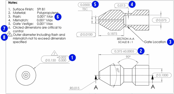
Adjust the part model to be at the midpoint of the tolerance range. For example, 0.150" +.002"/.000" would become 0.151", 0.001". Tooling engineers require room on each side of nominal to successfully build the tool. We see why lopsided tolerances exist in micro medical designs—especially when multiple components are designed to fit together—but avoiding them will greatly increase manufacturing success. It can be a tall order for designers to accommodate when the design is already in progress, so plan for symmetrical tolerances when you start your design.
2. MAKE IT POSSIBLE: AVOID nearly-impossible tolerances for a critical dimension
While manufacturing feature dimensions with extremely tight tolerances is achievable, sustaining their capability in long-term production is extremely challenging, depending on the part geometry. Passing a gauge R&R on a dimension with an extremely tight tolerance is nearly impossible unless there is a high level of dimensional certainty. It also can be beyond the capabilities of most tooling and measuring equipment.
3. BE FLEXIBLE: AVOID assigning poor gate locations
When possible, allow your molder to advise on gate location decisions, assessing the best entry point(s) for the plastic based on the tool design. A non-ideal gate location can result in dimensional instability; cause issues with filling, packing, knit lines, and sink; and highly influence the amount of gate vestige. For example, gating into a thin area of the part can result in gate freeze, creating problems with packing out the part.
4. KEEP IT TOGETHER: AVOID critical dimensions requiring cross-sectioning
Assigning a critical dimension to a cross-section view in a drawing is always discouraged. When you segment parts this small, there is a high level of uncertainty and variation in the measurements, resulting in an unreliable (and often unsuccessful) capability analysis. Typically, CT scanning offers a better solution for obtaining these measurements for non-critical dimensions.
5. KEEP IT REAL: AVOID critical dimensions including theoretical points
Any drawing callout for a measurement to a theoretical point with a tight tolerance should be avoided. If it cannot be avoided, avoid making the dimension critical. Otherwise, you will likely face capability challenges down the line which could cause significant delays to your timeline.
6. FLASH HAPPENS: AVOID unrealistic flash specifications
It is important to remember that flash always exists where two pieces of steel come together in injection molding and this needs to be accounted for in your part drawing. In your mold design review, your molder should identify potential flash areas. They can highlight areas that could be prone to flashing and help you create realistic tolerances for flash—or even design the tool to influence the direction of flash to not jeopardize your part’s designed function.
7. CRITICAL MEANS CRITICAL: AVOID more than 4 critical dimensions
We understand that every dimension on a micro medical design is important, but we recommend only designating up to four critical dimensions, if possible. During the design review, we encourage customers to identify the most critical dimensions to function as critical and rethink the less critical ones, which drives cost efficiency and optimizes lead time.
8. KEEP ’EM SEPARATED: AVOID including mismatch and flash measurements with drawing dimensions Keep flash and mismatch separate from your dimension. For example, a dimension tolerance of,.003" can be interpreted to mean the tolerance range includes flash and mismatch measurements. If mismatch, flash, and gate vestige are accounted for in a dimension tolerance, this infringes on the manufacturing tolerances and can result in a very low chance of success.
For more information, visit MTD Micro Molding's Web site.
Related Glossary Terms
- flash
flash
Thin web or film of metal on a casting that occurs at die partings and around air vents and movable cores. This excess metal is due to necessary working and operating clearances in a die. Flash also is the excess material squeezed out of the cavity as a compression mold closes or as pressure is applied to the cavity.
- tolerance
tolerance
Minimum and maximum amount a workpiece dimension is allowed to vary from a set standard and still be acceptable.
- web
web
On a rotating tool, the portion of the tool body that joins the lands. Web is thicker at the shank end, relative to the point end, providing maximum torsional strength.