To achieve the quality and productivity requirements for most precision grinding operations, it is necessary that the grinding wheel is trued and dressed prior to grinding and periodically during the grinding operation. The truing process is initially performed to correct for any wheel runout, create the required profile on the wheel and condition the grinding wheel face.
During the grinding operation it is usually necessary to dress the wheel periodically to re-establish the wheel profile and/or recondition the wheel face. Wheel conditioning, typically involves the sharpening and opening up of the wheel face, while also removing dull abrasives, excessive bond and workpiece material (loading). A sharp and open wheel face will allow maximum possible material-removal rates by minimizing the high grinding power and forces associated with a dull and closed wheel. On the other hand, there may be occasions when a closed and dull wheel face is required, such as to improve the surface finish. This process of preparing of the wheel face to the desired condition (roughness) is achieved during the dressing process and fine-tuned by modifying the dressing parameters, including the dressing speed ratio.
Truing and dressing a grinding wheel can be carried out using either stationary tools or rotary tools. As the names suggest, the rotary dressing tool rotates and the stationary tools do not. The main reason for selecting a rotary tool - also known as dressing roll - over a stationary tool is that it will greatly improve the dressing tool life and form holding capabilities. This is largely due to the greater number of active diamonds that are around the periphery of the roll. Although tool life is usually the chief driving force being selecting a rotary dresser over a stationary device, an additional benefit to rotating the dresser is the fact that the relative speed between the wheel and roll can be adjusted to influence grinding process. The dress ratio is the dress roll velocity divided by the grinding wheel velocity and can be either in a positive or a negative direction. This paper discusses the different rotary dressing methods and will cover in more detail how the dress speed ratio can be used to manage the wheel face condition and ultimately manage the grinding process including, workpiece quality and process productivity.
Types of Rotary Dressing
There are several rotary dressing methods including:
- Traverse profile dress
- Form roll plunge dress
- Intermittent dress
- Continuous dress (CD)
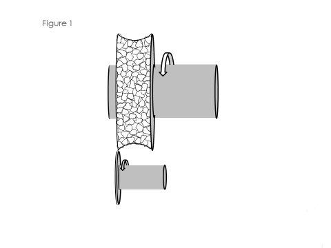
Figure 1 - Traverse dress action. All photos courtesy of Norton | Saint-Gobain
A traverse, profile dress process involves the dressing tool moving across the grinding wheel at a predetermined depth of dress and dress feed rate. The wheel would be dressed prior to starting the grind and periodically as needed during the grinding operation. The dressing tool will either be rotating in the same direction as the grinding wheel (uni-directional) or the opposite direction of the grinding wheel (counter-directional). The traverse dressing action can dress the wheel face straight or with a complex form. Figure 1 shows the toolpath for a concave wheel profile, and Figure 2 shows a typical traverse dressing tool.
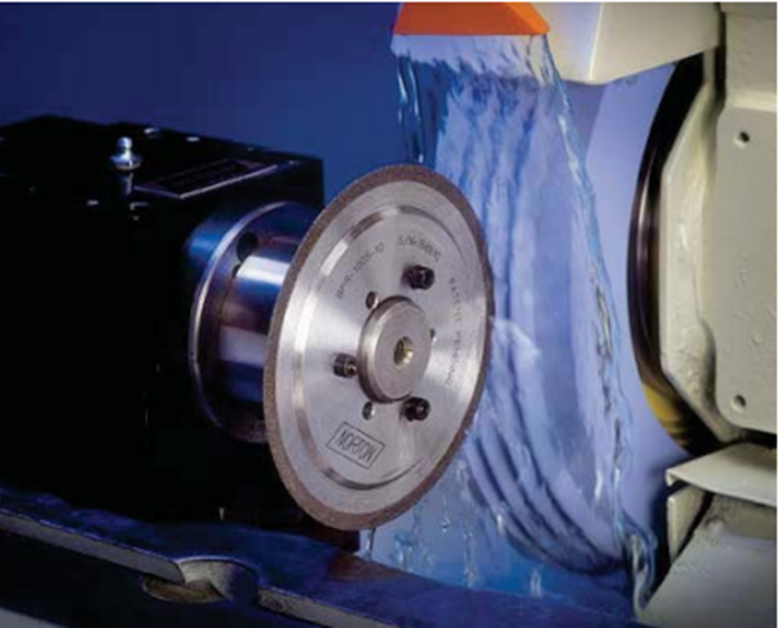
Figure 2 - Cylindrical grind traverse dress.
A form roll plunge dress process involves the grinding wheel plunging into the roll with no traverse motion. The diamond dress roll is the inverse form of the form required on the wheel. As with the traverse dressing, the form Roll plunge method can dress the wheel face straight or with a complex form. Figure 3 is a diagram that shows the wheel plunging into the dress roll, creating a concave form. Figure 4 shows an example of a dress roll with a complex form.
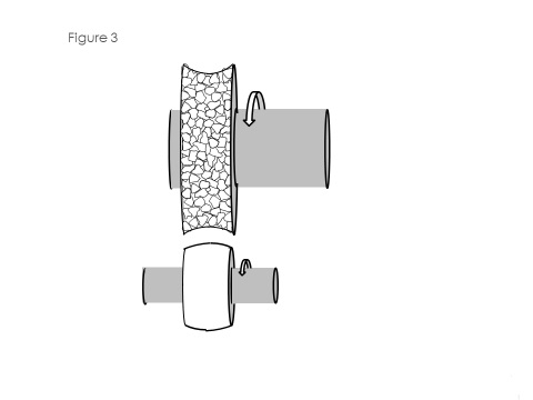
Figure 3 - Form roll plunge dress action.
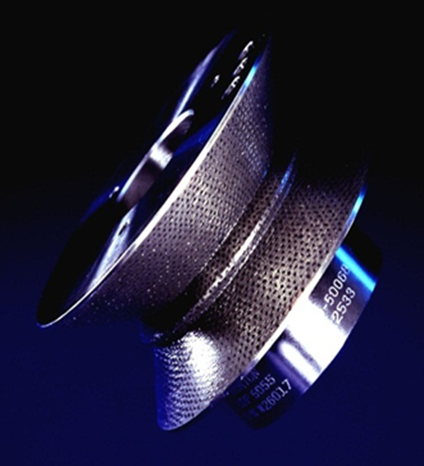
Figure 4 - Form dress roll.
A form roll plunge dress process can be either be an intermittent-type dress or a continuous-type dress (CD). A form roll plunge dressing using an intermittent dress cycle is a dressing method where, after the initial dress, the wheel would be dressed at periodic intervals during the grinding cycle using a form dress roll. The grinding operations would involve removing a certain amount of material or grinding a certain number of parts before dressing. For example, 10 grinding passes might be made on the workpiece and then the wheel would be dressed to re-establish the wheel form and/or wheel face sharpness.
A form roll plunge using a CD process is a dressing cycle that continuously dresses the grinding wheel during the grinding cycle. This type of dressing operation is common in creep-feed processes used in the automotive and aerospace industries. A major advantage of CD, particularly in creep-feed applications, is that the grinding wheel stays sharp and open throughout the grind. A sharp and open wheel keeps the grinding power low and allowing for high material-removal rates without form loss or workpiece burn.
Although this paper only covers the dress speed ratio, it should be known that this is not the only dressing parameter that needs to be considered when setting up or making adjustments to a dress cycle. Table 1 lists the key dressing parameters. All of these parameters can have a significant effect on the dressing and grinding process, however only the dress speed ratio applies to all three previously described rotary dressing methods: traverse profile dress, form roll plunge - intermittent dress, and form roll plunge - continuous dress.
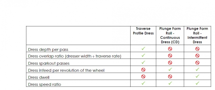
Table 1 - Dressing parameters.
Dress Speed Ratio
The dress speed ratio is the relationship between the dress roll velocity (Vr) in sfm or m/sec and the grinding wheel velocity (Vs) in sfm or m/sec. and can be calculated using the following equation: Speed ratio = Vr ÷ Vs
The dress speed ratio can be a positive or a negative value as shown in Figure 5. A positive value represents when the dresser rotation and the wheel rotation are the same direction at point of contact (uni-directional). A negative value represents when the dresser and the wheel are in an opposite direction at the point of contact (counter-directional).
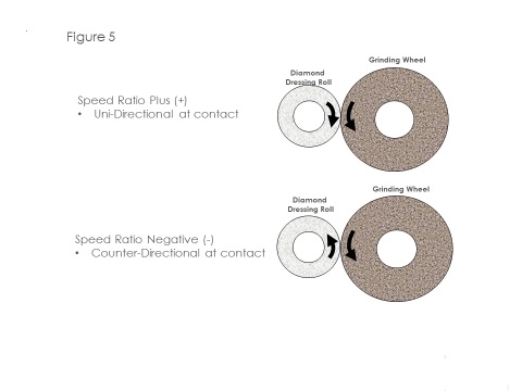
Figure 5 - Positive and negative speed ratios.
Figure 6 shows the relative wheel face roughness and the relative dressing forces as a function of the speed ratio settings. This figure shows that the wheel face roughness gradually increases when moving from the negative speed ratio to the positive speed ratio (right to left). This means that a grinding wheel dressed at positive speed ratio will be sharper and more open than a wheel dressed at negative speed ratio.
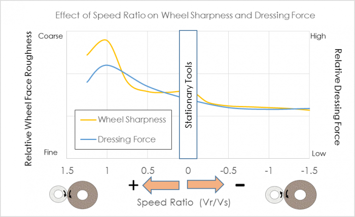
Figure 6 – Effect of speed ratio on wheel sharpness and dressing.
A sharper and open wheel will grind at lower power and force and, therefore, allow for higher material-removal rates, with less chance of burn. However, a sharper wheel will also result in coarser workpiece surface finish. A dull and closed wheel will typically result in a finer workpiece surface finish but it will grind at higher power and forces, possibly resulting in material damage (burn).
Dressing forces also increase when moving from the negative speed ratio to the positive speed ratio (right to left). The dressing forces are important when it comes to dressing tool life, in that high dressing forces reduce dresser life. Therefore, in situations where dresser roll life is an issue, negative speed ratios are utilized.
Figure 6 shows that as the speed ratio approaches +1, the wheel sharpness and dressing forces increase dramatically. At +1, the wheel and roll are running in the same direction and at the same speed (velocity), literally crushing the wheel face. This is known as the crush speed. Approaching the crush speed will change the dressing action from shear forces and attritious grain wear to high compressive force and the crushing of the grain and bond. These high compressive forces can result in damage to the abrasive grain and wheel bond.
Dressing at or close to the crush speed requires the grinding machine and dressing system to have good dynamic and static stiffness to prevent vibration and deflection while dressing. Also, the dresser motor must have enough torque to avoid stalling or a reduction in speed during dressing. Excessive forces during dressing can lead to chatter on the grinding wheel face, as well as poor roll life and dressing unit life. For all of these reasons, it is generally not recommended to operate above a +0.8 dress speed ratio.
The range typically recommended for conventional abrasive vitrified wheels is from +0.2 to +0.8. Table 3 shows the recommended speed Ratios for various grinding wheel specifications. Hard wheel specifications, like diamond vitrified and metal-bond wheels, are typically dressed at a negative speed ratio where the dressing forces are lowest to help improve dresser tool life.
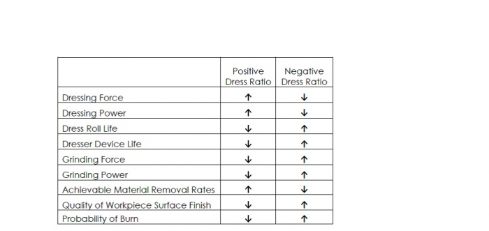
Table 2 – Speed ratio impact on grinding process.
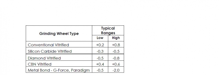
Table 3 – Typical recommended speed ratio ranges.
Table 2 shows the relative impact the dress speed ratio can have on the dressing and grinding process outputs. Notice that when the dressing force and power increases, the grinding forces and power decrease and the surface finish quality decreases, or gets rougher. This is a result of the wheel face being sharper and more open. Lower dressing forces and power will result in the grinding power and force being higher and improved surface finish quality. This is a result of the wheel face being duller and less open. An example of using the dress speed ratio to alter the sharpness and openness of the wheel to directly influence the grinding power, grinding force and workpiece surface finish, is given in the following case study.
Table 3 shows general speed ratio guidelines for various wheel specification. These are general guidelines, so please contact your dressing tool supplier for the dressing speed ratio that is appropriate for a particular process.
Case Study
The following was a grinding case study that evaluated the dress speed ratio and its effect on grinding power, grinding force and workpiece surface finish. The dressing process was an intermittent plunge dress using form roll.
Several test grinds were carried out where the wheel was dressed and then the workpiece was ground, each time keeping everything the same with the exception of changing only the dress speed ratio. The range of speed ratios tested were between +0.9 and -0.9. Figures 7 and 8 shows that moving from +0.9 to -0.9 increased the grinding power from 4 hp to 7.5 hp and the grinding force from 100 lbf to 140 lbf. This is an indication that the grinding wheel face is duller when dressed in a negative mode (counter-directional) as compared to a positive mode (uni-directional). This is also evident in Figure 9 where it is shown that the workpiece surface finish is improving when moving from positive to negative, resulting in the finish going from 38 µin. Ra to as low as 25 µin. Ra. This again indicates that the wheel is duller when dressed in a negative mode (counter-directional) compared to a positive mode (uni-directional). Figure 10 shows the workpiece, and Table 4 the test conditions.
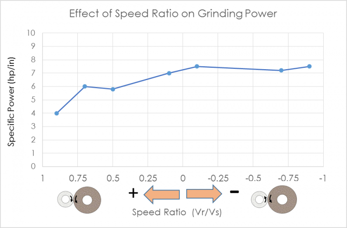
Figure 7 - Grinding power.
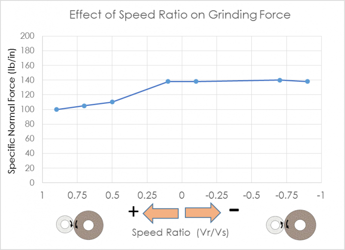
Figure 8 - Grinding force.
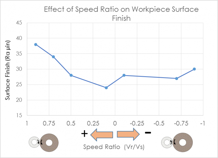
Figure 9 - Workpiece surface finish.
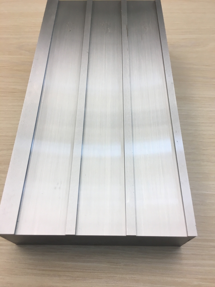
Figure 10 - Test workpiece sample.
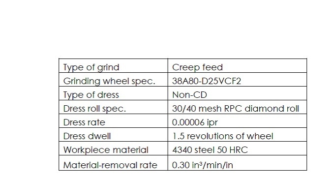
Table 4 - Test conditions.
Conclusion
Selecting the correct dress speed ratio can have a significant influence on the technical and economic outcomes of a grinding operation. By modifying the relative speed between the wheel and dress roll, it is possible to improve the quality of the workpiece being ground and/or increase the material-removal rates to improve productivity. The dress speed ratio can also be adjusted to help avoid process issues that include material burn, workpiece chatter, poor dresser life, etc. Therefore, a good understanding of the effects of the dress speed ratio on the grinding process is essential to truly optimize a new or existing grinding process.
References:
- Handbook of Machining with Grinding Wheels - Marinescu, Hitchiner, Uhlmann, Rowe, Inasaki.
- Principles of Modern Grinding Technology - W. Brian Rowe
Related Glossary Terms
- abrasive
abrasive
Substance used for grinding, honing, lapping, superfinishing and polishing. Examples include garnet, emery, corundum, silicon carbide, cubic boron nitride and diamond in various grit sizes.
- chatter
chatter
Condition of vibration involving the machine, workpiece and cutting tool. Once this condition arises, it is often self-sustaining until the problem is corrected. Chatter can be identified when lines or grooves appear at regular intervals in the workpiece. These lines or grooves are caused by the teeth of the cutter as they vibrate in and out of the workpiece and their spacing depends on the frequency of vibration.
- dressing
dressing
Removal of undesirable materials from “loaded” grinding wheels using a single- or multi-point diamond or other tool. The process also exposes unused, sharp abrasive points. See loading; truing.
- feed
feed
Rate of change of position of the tool as a whole, relative to the workpiece while cutting.
- grinding
grinding
Machining operation in which material is removed from the workpiece by a powered abrasive wheel, stone, belt, paste, sheet, compound, slurry, etc. Takes various forms: surface grinding (creates flat and/or squared surfaces); cylindrical grinding (for external cylindrical and tapered shapes, fillets, undercuts, etc.); centerless grinding; chamfering; thread and form grinding; tool and cutter grinding; offhand grinding; lapping and polishing (grinding with extremely fine grits to create ultrasmooth surfaces); honing; and disc grinding.
- grinding machine
grinding machine
Powers a grinding wheel or other abrasive tool for the purpose of removing metal and finishing workpieces to close tolerances. Provides smooth, square, parallel and accurate workpiece surfaces. When ultrasmooth surfaces and finishes on the order of microns are required, lapping and honing machines (precision grinders that run abrasives with extremely fine, uniform grits) are used. In its “finishing” role, the grinder is perhaps the most widely used machine tool. Various styles are available: bench and pedestal grinders for sharpening lathe bits and drills; surface grinders for producing square, parallel, smooth and accurate parts; cylindrical and centerless grinders; center-hole grinders; form grinders; facemill and endmill grinders; gear-cutting grinders; jig grinders; abrasive belt (backstand, swing-frame, belt-roll) grinders; tool and cutter grinders for sharpening and resharpening cutting tools; carbide grinders; hand-held die grinders; and abrasive cutoff saws.
- grinding wheel
grinding wheel
Wheel formed from abrasive material mixed in a suitable matrix. Takes a variety of shapes but falls into two basic categories: one that cuts on its periphery, as in reciprocating grinding, and one that cuts on its side or face, as in tool and cutter grinding.
- static stiffness
static stiffness
Relates to the machine tool and is measured in pounds per inch. Static stiffness indicates how many pounds of force it takes to deflect the spindle a linear distance of 1" in a given direction. See dynamic stiffness; stiffness.
- stiffness
stiffness
1. Ability of a material or part to resist elastic deflection. 2. The rate of stress with respect to strain; the greater the stress required to produce a given strain, the stiffer the material is said to be. See dynamic stiffness; static stiffness.
- toolpath( cutter path)
toolpath( cutter path)
2-D or 3-D path generated by program code or a CAM system and followed by tool when machining a part.
- truing
truing
Using a diamond or other dressing tool to ensure that a grinding wheel is round and concentric and will not vibrate at required speeds. Weights also are used to balance the wheel. Also performed to impart a contour to the wheel’s face. See dressing.
Author

John Hagan is senior application engineer with Norton | Saint-Gobain, 9 Goddard Road, Northboro, Mass., 01532. He may be reached via email at [email protected].