Cool the tool with efficient new cutting tool solutions
Cool the tool with efficient new cutting tool solutions
A tool manufacturer overcomes the challenges of excessive heat generation in the cutting zone.

 One of the main tasks in metal cutting is to efficiently extract the enormous heat generated during cutting. This is a challenge, especially in turning work where there is continuous contact between the cutting edge and the workpiece.
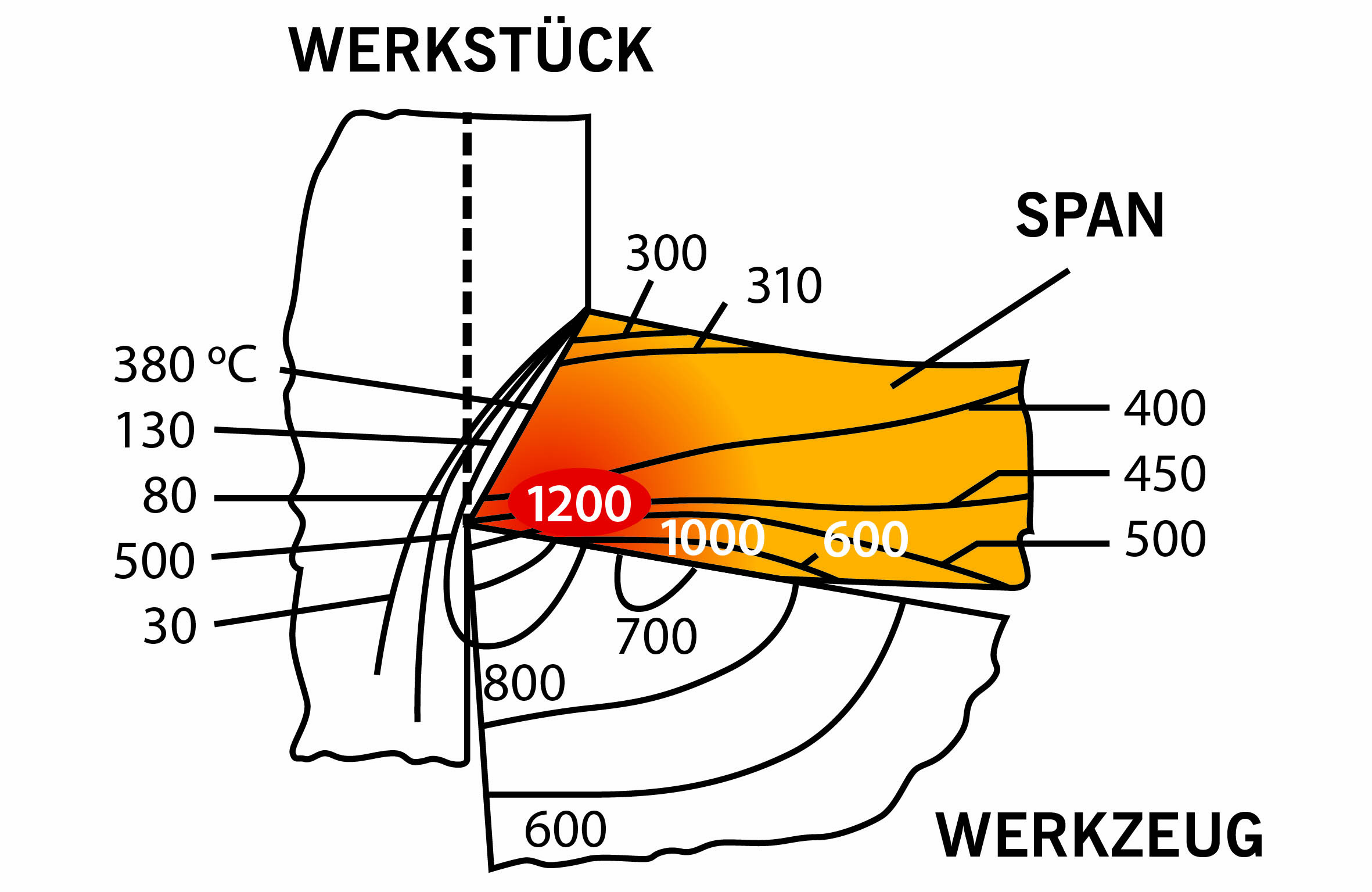
While a large part of the heat generated by turning is dissipated in the chip, the temperatures prevailing in the cutting zone and the heat can reach temperatures in excess of 1000 degC, depending on the material, feed and rpm. This activates thermal processes that cause the cutting tool to wear more quickly. In extreme cases, the tool can even burn out after a short time. A more positive geometry and cutting speed adapted to the process may provide a superficial remedy, but this either causes long-term costs or lowers productivity.
Flooding the cutting zone, the commonly used external cooling method, is not precise in application and its true effect is limited. In fact, the relatively imprecise and uncontrolled flooding of coolant or oil into the cutting process cools the chips instead of the cutting edge. In many cases, the high temperature differences at the cut point cause a thermal shock that fatally damages the cutting edge.
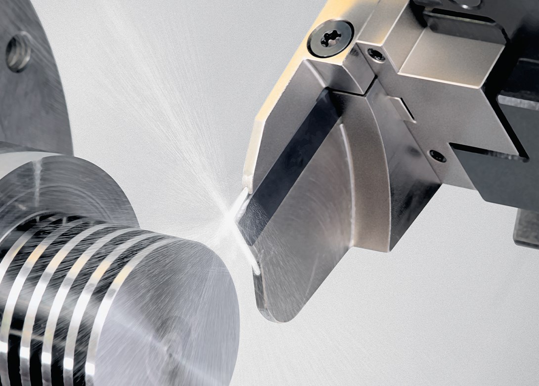
 Instead of flooding the cutting zone, tool manufacturer ARNO Werkzeuge says there are better solutions, including the ARNO Cooling System (ACS) that succeeds in feeding coolant directly to the cut point via two channels from the top and from the bottom.
ARNO Werkzeuge developed the field-proven ACS system in two variants. With the ACS1 variant, the coolant jet is guided along the insert seat in a coolant channel and emerges directly at the cutting zone. The coolant then effectively goes under the chip and optimally flushes it out of the cutting zone.
With the ACS2 variant, the coolant channel at the insert seat is coupled with a second flow-optimized coolant jet from the bottom onto the tool flank. The latest developments offer this coolant channel with a triangular outlet that supplies coolant across the full width of the insert right through to the edge.
The internally guided coolant jet always goes precisely to the cutting zone and the tool flank. It also minimizes the risk of material build-up on the cutting edge and the associated crumbling of the cutting edge.
Additive manufacturing advances
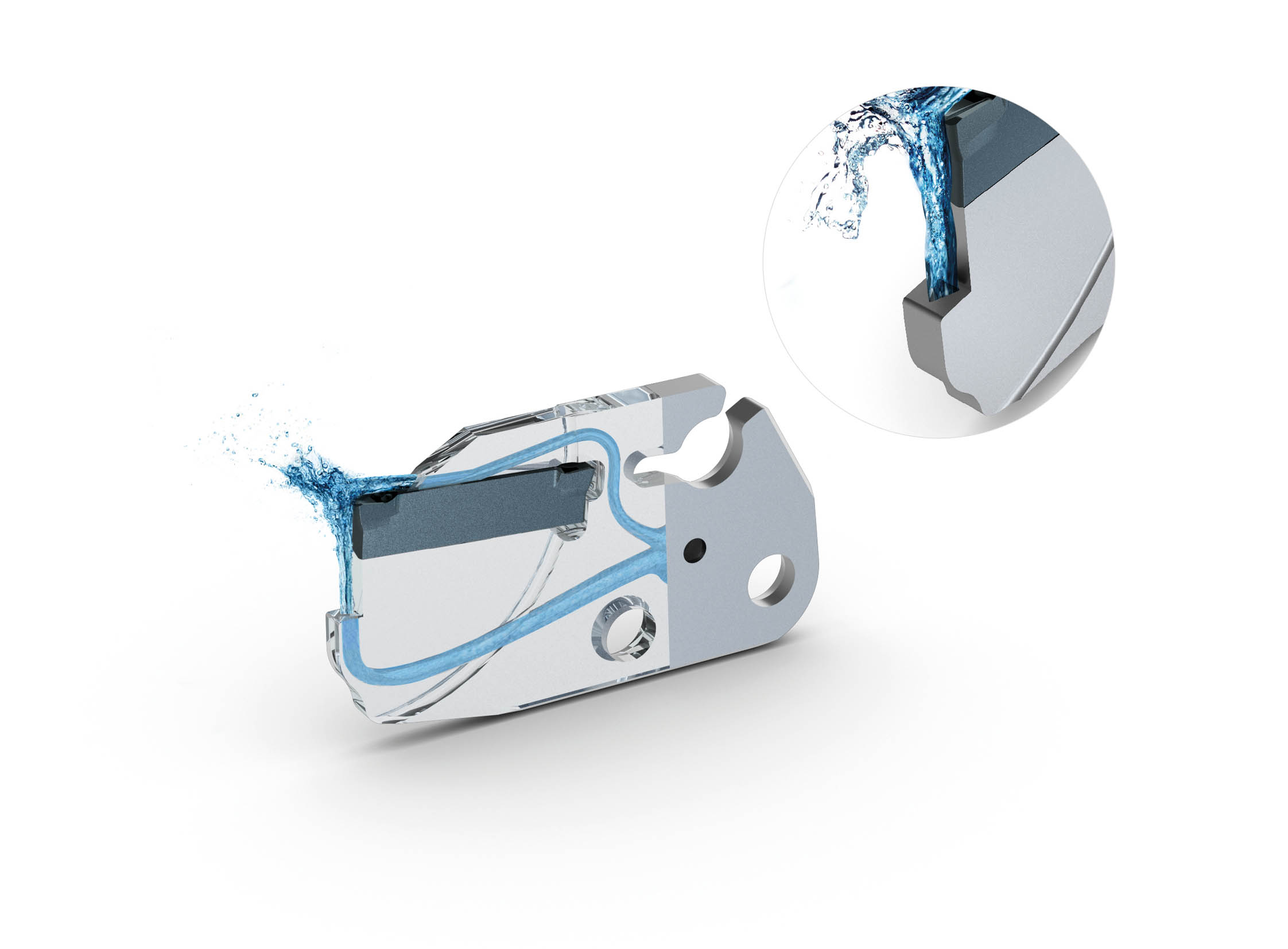 ARNO utilized additive 3D printing methods to produce advanced technology part-off modules. This method permits the production of a triangular shaped coolant outlet to control the coolant jet to maximum cooling with minimum consumption and to 'flood' the furthest edge of the tool flank.
These optimized cooling conditions also permit further potential optimizations, such as a reduction in insert width.
The ACS2 feeds coolant under the chip and flushes it more easily out of the cutting zone. Chips are shorter and the tendency for built-up edge insert conditions are greatly reduced. Measurements confirm that this coolant method reduces temperature by about half. As a result, the tool is exposed to much less stress and flank wear is considerably reduced. Instead of having to lower cutting and feed rates to protect the tool, rates can even be increased, the company says.
Productivity rises since tool life is significantly longer. Users report that their tools last up to three times longer or at least twice as long. Fewer tool changes ultimately relieves the work burden on operating personnel. Not to mention significantly reduced machine down time.
It also allows users to maintain inner cooling without tubes and interfering edges even during tool changes. Users need not do without direct cooling, even in turning operations. With the right tool holder, the integrated channels feed coolant close to the cutting zone. No complex adjustments are needed since the plug-and-play system always fits. Optionally, the manufacturer offers a VDI holding tool to match the tool holders and it feeds coolant to the holder without any pipe or hose connections.
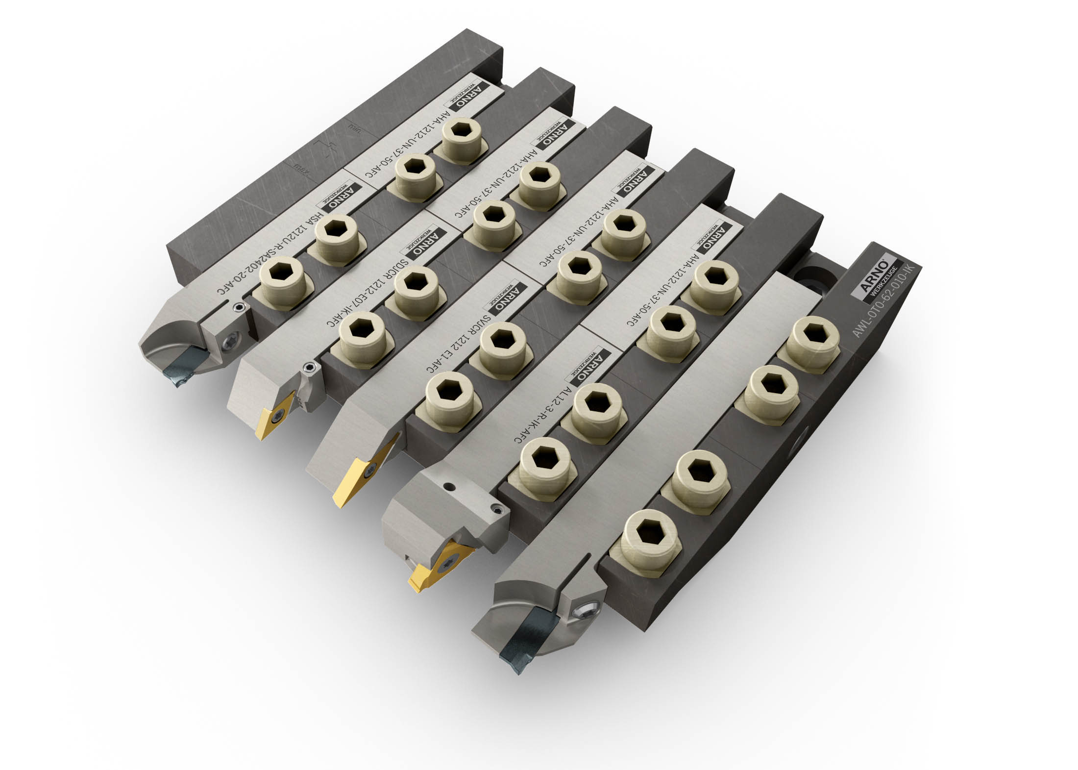 Integrated cooling is even possible on sliding head lathes where tools must be frequently changed. To achieve this, ARNO Werkzeuge recommends its AWL sliding heads tooling solution and the AFC quick-change tooling system. The AWL tool holder system offers solutions for a wide range of sliding head lathe manufacturers machine tools.
The AFC quick-change tool holders are mounted on a fixed stop and the required insert can be fitted or removed via two quick release clamping screws. Two separate cooling channels in the tool holder system can be opened or closed to permit tools with and without through-tool cooling to be used in parallel.
It is almost always beneficial to use tools with through tool cooling wherever possible. And, when a tool manufacturer understands the user's manufacturing scenarios and has also given a lot of thought to the process such as the case with the ACS and the AWL, productivity receives a real boost.