Generally, when using abrasive wheels to grind parts, a dressing tool is required to maintain form and finish within specifications. Several options exist when choosing the type of dressing tool for an operation. These include single-point diamond tools, diamonds blade tools, form or plunge roll diamond wheels and “rotary single-point,” or “traversing rotary,” dressing.
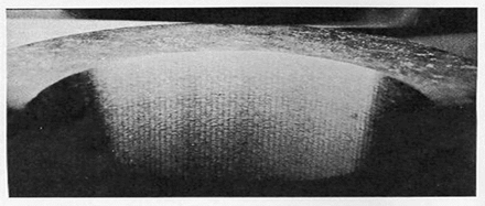
An internally ground part with chatter marks.
Traverse rotary dressing of grinding wheels has many advantages, including:
- Flexibility of form and finish
- Long life
- Consistent performance through life
- Low dressing forces
- Reduced tooling costs
Because of these advantages, this method of dressing has become very popular in recent years.
A plan view of the setup for traverse rotary dressing of grinding wheels is shown in Figure 1.
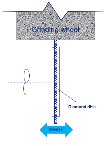
Figure 1
In a perfect world that would be the end of the story, but in any real mechanical system there are errors. In this system a number of errors can be introduced,including:
- Diamond concentricity errors (due to mounting or manufacturing)
- Dressing system balance errors
- Errors caused by external vibration (e.g. spindle bearings)
Because patterns that are a fraction of a micron deep can be seen with the naked eye on finished ground parts, these errors can cause undesirable visual patterns. The patterns can vary from "straight-line chatter" to "spiral" to "orange peel" defects.
A typical side view of a rotary dressing system is shown in Figure 2.
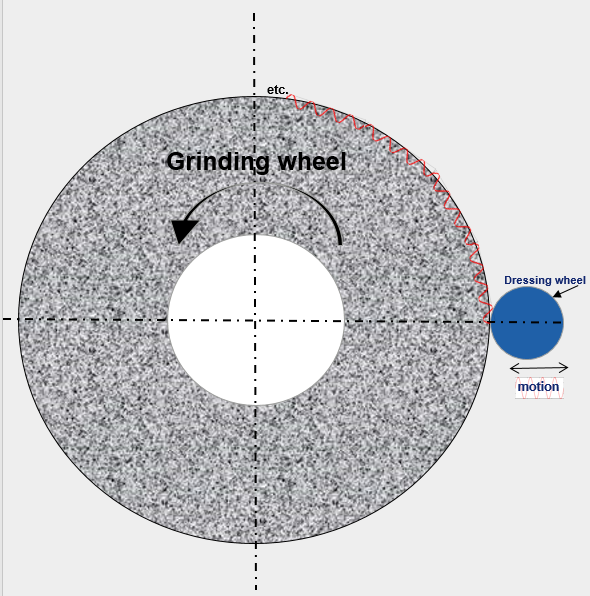
Figure 2
Unfortunately, these errors generally manifest themselves as a pattern on the OD of the grinding wheel. Experience indicates that most often the patterns are caused by once-per-revolution errors of the diamond disk, such as runout and balance. Once the pattern is formed on the OD of the grinding wheel, it will ultimately be transferred to the part during grinding.
Identifying the dresser as the source of the problem can be done by counting or calculating the chatter marks on one revolution of a part and multiplying this number by the finish work speed. If the product is close to dresser speed or multiples of dresser speed, then:
- Adjustments to dresser rpm need to be made
- Diamond runout should be checked
- Dresser balance should be checked
- Diamond mounting tolerances should be checked. Normally a diamond will have an interference fit.
The marks per revolution can sometimes be obtained as undulations per revolution from roundness checking equipment.
This article only considers straight-line chatter caused by the dressing disk. A more general approach, which will address different patterns generated during dressing, will be covered in a separate paper.
Understanding the Patterns
To understand the mechanisms involved, two topics are important. The first is the concept of "overlap factor" (Figure 3).
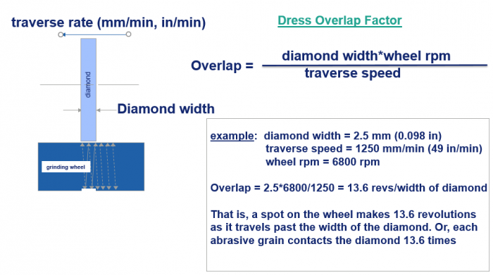
Figure 3
In the instance being discussed here, a wave pattern generated by the diamond would be over written 13.6 times as the dresser traverses by. So, how does this affect the pattern that gets transferred to the wheel?
First, consider what happens if the ratio of the wheel to diamond rpm is an integer (Figure 4).
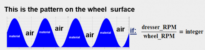
Figure 4
The pattern will never change. The bumps and valleys on the wheel will match the high and low points of the diamond every time the wheel rotates, much like two gears meshing together. When this happens, the entire amount of the dresser "motion" will be imprinted on the wheel. In this case, the overlap factor will not matter, and straight-line chatter will be produced.
If there is a phase change, i.e. the ratio of dresser rpm to wheel rpm is not an integer, the amplitude of the pattern will be reduced as the wheel rotates multiple times. Figure 5 illustrates what happens when the ratio is an integer +0.5.
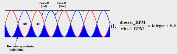
Figure 5
There are a number of interesting things to note about this condition:
- It is stable after two wheel rotations, so the overlap factor only needs to be two to get full benefit of the "interference" caused by the phase change.
- There are twice as many “bumps” with the same dresser rpm.
- A fast Fourier transform of this pattern would produce a lot of harmonics (multiples) of dresser rpm but not necessarily a peak at dresser rpm.
- The pattern is half the amplitude of the original pattern (Figure 4).
So the ratio of an integer +0.5 is an improvement, but will still be half the amplitude of the dresser motion. Next, let’s look at a ratio of an integer +0.25 (90 degree phase shift).
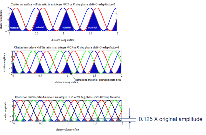
Figure 6
Figure 6 shows the progressive reduction of the pattern as the overlap factor is increased to four. Increasing the overlap factor more than this will not reduce the amplitude of the pattern further.
Using this method of analysis, these results can be displayed graphically. Using a wheel-to-dresser-rpm ratio of 1.083, Figure 7 illustrates what happens as the number of overlaps increases from one to 12.
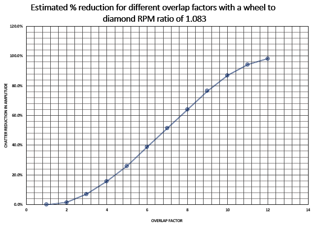
Figure 7
Based on this method of analysis, Table 1 lists the phase shifts and corresponding overlap factors what will minimize chatter.
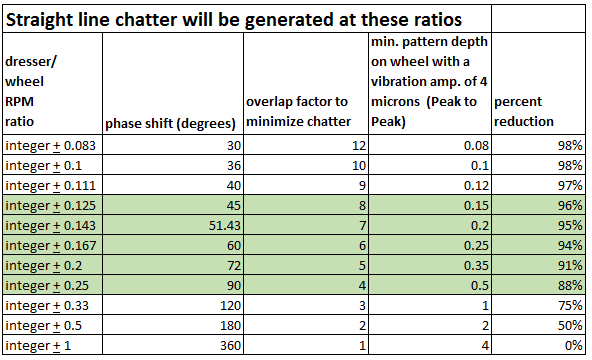
Table 1
Discussion
To bring this closer to implementation in the real world, several issues need to be addressed:
- Knowing the exact speed of the dresser and the wheel can be a problem. The errors can be significant when trying to avoid patterns.
- Many times the overlap factor is used to adjust the surface finish, making it difficult to adhere to the ratios listed. If the finish cannot be adjusted by using wheel to dresser speed ratio, dress depth amount, wheel speed or cycle changes, a different wheel specification should be considered.
Recommendations
Some rules of thumb can be developed from this analysis. It appears that dresser to wheel ratios of an integer +0.08 to +0.25 would be the best range to be in. However, if the diamond/wheel rpm ratio is less than an integer +0.125, the ratio is too close to 1, a small error would multiply the chatter amplitude many times. Therefore, the recommended range is an integer +0.125 to +0.25 (the green highlighted area in Table 1).
The recommended overlap factor for CBN is three. This does not cover many ratios in Table 1, but, fortunately, CBN wheels generally “round up” diamonds, so dresser induced chatter is not a problem unless there is another disturbing frequency involved.
The Norton iGrind App, available as a free download at https://www.nortonabrasives.com/en-us/igrind, recommends 12 as the overlap factor for traverse rotary dressing of an aluminum-oxide wheel. This is a good place to start, as it covers all the dresser to wheel ratios listed in Table 1.
Related Glossary Terms
- abrasive
abrasive
Substance used for grinding, honing, lapping, superfinishing and polishing. Examples include garnet, emery, corundum, silicon carbide, cubic boron nitride and diamond in various grit sizes.
- chatter
chatter
Condition of vibration involving the machine, workpiece and cutting tool. Once this condition arises, it is often self-sustaining until the problem is corrected. Chatter can be identified when lines or grooves appear at regular intervals in the workpiece. These lines or grooves are caused by the teeth of the cutter as they vibrate in and out of the workpiece and their spacing depends on the frequency of vibration.
- cubic boron nitride ( CBN)
cubic boron nitride ( CBN)
Crystal manufactured from boron nitride under high pressure and temperature. Used to cut hard-to-machine ferrous and nickel-base materials up to 70 HRC. Second hardest material after diamond. See superabrasive tools.
- dressing
dressing
Removal of undesirable materials from “loaded” grinding wheels using a single- or multi-point diamond or other tool. The process also exposes unused, sharp abrasive points. See loading; truing.
- grinding
grinding
Machining operation in which material is removed from the workpiece by a powered abrasive wheel, stone, belt, paste, sheet, compound, slurry, etc. Takes various forms: surface grinding (creates flat and/or squared surfaces); cylindrical grinding (for external cylindrical and tapered shapes, fillets, undercuts, etc.); centerless grinding; chamfering; thread and form grinding; tool and cutter grinding; offhand grinding; lapping and polishing (grinding with extremely fine grits to create ultrasmooth surfaces); honing; and disc grinding.
- grinding wheel
grinding wheel
Wheel formed from abrasive material mixed in a suitable matrix. Takes a variety of shapes but falls into two basic categories: one that cuts on its periphery, as in reciprocating grinding, and one that cuts on its side or face, as in tool and cutter grinding.
- micron
micron
Measure of length that is equal to one-millionth of a meter.
- outer diameter ( OD)
outer diameter ( OD)
Dimension that defines the exterior diameter of a cylindrical or round part. See ID, inner diameter.