Article provided by Epson America Inc.
From assembly and pick-and-place to material handling and packaging, the use of robots is on the rise in factory automation. Extremely customizable in even the most complex applications, automation systems are beneficial for a variety of reasons. Taking the plunge into automation, however, can be confusing and daunting. With so many factors to consider, you may be wondering where to start. This guide is a broad overview, but can serve well as a starting point for those new to automation.

Photo courtesy of Epson America
Why Automate?
To best determine where to place your focus in the automation process, the first step is to ask yourself, “Why am I thinking about automating my current process?” The answer may lie within one or more of the following areas:
Cost—Do you need to reduce your current cost per unit?
Volume—Do you need to see an increase in volume, but lack the resources to do so?
Quality—Are your deliverables turning out perfectly each and every time, or are there quality issues?
Precision—Are your parts too small or the precision requirements too tight for humans to handle?
Safety and Repetitive Motion—Are the materials you are handling unsafe for humans to work with, or are repetitive motions causing human injury?
Understanding your primary reasons for automating will help you focus on the right areas as you begin your automation project.
Know Your Process
Now that you’ve determined why you want to automate, your next step is to analyze your current process. By doing so, you’ll be able to determine which steps in the process are the most critical and might benefit from automation.
Think about your current process for building products. Is it documented? Can you explain it clearly to someone who’s not familiar with your process? Begin thinking about how you would document or explain your current process and then offer ideas on how to automate. Consider questions like:
● Where to the components come from?
● What are the assembly steps?
● What sort of jigs or special tools are required for your current process?
There are product and assembly design processes that should be considered when transitioning from a manual operation to an automated operation. Design for assembly (DFA) is a method used to analyze components and minimize costs by optimizing the assembly process and reducing the number of parts used. Utilizing this method will help determine if you need to change parts or steps in your process when making the switch from manual assembly to automation.
Understanding and being able to explain your current process is a critical step as it can be used to identify the strong and weak points that can be improved upon in your automation solution.
Problem areas can range from bottlenecks in your process to poor-quality parts. Think about the problem areas associated with your current process. Consider the following:
● What is currently slowing down your automation process?
● Are there easily identifiable bottlenecks?
● Are you consistently experiencing failures that require rework?
● Is the final product meeting your current quality standards?
● Are you producing enough product in a timely fashion?
● Are your costs to manufacture too expensive using your current process?
Let’s use an example to help clarify identifying problem areas. Assume you have a team of assemblers building a product with a molded plastic body and two metal inner parts. The process today is that an assembler pulls a plastic body shell out of a bag and places it in a fixture. Next, he grabs two metal parts from separate bins and slides them into slots on the plastic body. Then, he fastens the metal parts with an electric screwdriver. Sounds simple, right? On the surface, it may, but the potential for quality issues is huge, given the number of things that could go wrong. Let’s list just a few areas of concern:
Variety of plastic body shells—If there are several types, how do you keep them separated and make sure the correct one is used for each process?
Deviation of part tolerance—Many times, we tend to believe that the process doesn’t work because of human error, but have you considered that the parts themselves may be out of tolerance?
Proper part insertion (right-side-up issue)—Sometimes parts can be inserted two or more different ways, but only one way is correct. How do you make sure parts are always inserted right side up?
Screw driving issues—How do you ensure that all the screws are fastened properly?
Each of these items could be related to quality. But, they could also be related to cycle times. Which steps in the process take the most time? Which are the most prone for rework or readjustment and therefore take more time? Which might be too repetitive and therefore cause pain and injury to your workers? These could all be considered problem areas in your current process and are just a few items from one simple example.
Knowing your problem areas will help in creating a solid automation solution moving forward. Sharing this information with allow a robot expert, systems integrator or other outside experienced party to more easily find the most effective solution.
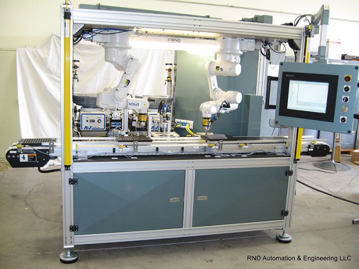
Photo courtesy of RND Automation & Engineering
Identify Your Requirements
To build the best system for your process, you will need to identify key requirements that are central to your business and prioritize them based on importance. There are three areas that must be considered for every robot-based application: speed, precision and payload. These areas require prioritization because, for most applications, you must compromise between them. This means that you will need to decide which is the most critical.
For example, there are applications where customers request the absolute fastest speed possible because their parts per minute (PPM) cycle rate is critical. In these cases, we focus on activities to reduce overall cycle times, such as reducing tooling weight or optimizing motion paths. Other times, precision is critical. In those cases, we might reduce speeds and tooling payloads to enhance precision. The amount of tradeoff will vary from application to application. The important takeaway here is to know the requirements for your specific application.
Some key requirements that you will need to identify for every application are:
Precision—Many customers simply aren’t sure of their precision requirements. While Epson robots have repeatability down to 5µm, most applications in the small assembly arena range from 25µm to 200µm in terms of precision requirements. Look at the components you are assembling and the tolerances required for the parts to be placed reliably. A qualified robot vendor or systems integrator can help you define placement tolerances for your application. This is an area where a target is required because it will affect all aspects of the overall solution.
Payload—A common misconception is that payload is defined by only the weight of the part being moved. Payload, from a robot usage perspective, is the total weight put on the end of the arm, which also includes tooling such as a gripper. Usually, for smaller parts, the tooling weighs much more than the parts, so be sure to consider both the maximum part weight and the tooling weight when defining the maximum payload. Also, keep in mind that while robots are rated with maximum payload specifications, it is sometimes a good idea to move up to a larger robot when you get close to the maximum. This is an area where the robot vendor can guide you in selecting the proper robot for an application.
Cycle Time—How many parts do you need to produce each week? Knowing this will allow you to use a simple calculation to determine cycle time or PPM required for the robot automation system. With a cycle time in hand, the robot vendor or systems integrator can help determine which robot(s) to use for an application and whether or not a multiple-robot system will be required. There are many ways to improve total throughput, including multiple-headed tooling and motion optimization.
Reach—Things like part size and distance required to move them are used to determine reach. Robot vendors and system integrators can help define reach requirements. However, they will need to understand the total process and all parts required in the work cell. By understanding the layout, reach can be determined and a robot with the appropriate reach capacity can be selected.
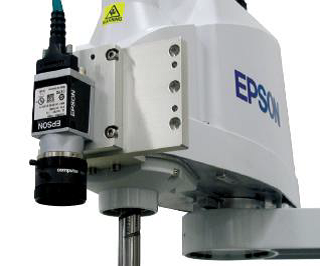
Epson G3 SCARA robot with a mounted mobile camera as part of the Epson Vision Guide option. Photo courtesy of Epson America
Automation Components
Once you’ve defined your process and identified your requirements, it’s time to start putting together your wish list of components. There are a number of factors to consider at this phase in your planning.
Parts Presentation—How will your parts get to the robot? Bowl feeder, flexible feeder or some type of conveyor? Also, think about any fixtures you might need during product assembly. Many systems require special fixtures that hold parts in place or flip parts during assembly.
Vision—If the parts cannot be fed within proper tolerances, vision may be required and integrated with the robot for precise pickup or placement. Vision may also be required for inspection of components or finished assemblies.
End-of-arm Tooling—EOAT encompasses all of the devices attached to the end of a robot’s arm to help the robot grasp and work with parts. From pneumatic devices to mechanical grippers, EOAT is vital to every robot automation application. While standard grippers can be used for some applications, custom tools are often required for higher speed or higher precision applications. Use an experienced tool designer to define and build your EOAT.
Factory Standards—Do you have a standard fieldbus communications platform within your factory? Do you use Ethernet/IP or ProfiNet? Are there other standards you need to consider and let your systems integrator know about?
Base—Every robot will need a base. The more mass that is moving, the more rigid the base will need to be to allow for fast motion and high precision. We have seen many situations where a lightweight or light-rigidity robot base moves when the robot moves. This slows down cycle times or requires the system to stabilize before placing components because of vibration. The base is the core for your system, so be sure to select or build an appropriate base, depending upon cycle time and precision requirements.
Manpower—Who Will Build It?
By now, you’ve figured out why you want to automate, what your current process is, the requirements needed to maximize automation and many of the components needed for you to build the robot automation system required for your products. With all of these areas identified, the next logical question is “Who will build the system?” The answer may be within your company, or you may need to look outside. Chances are, you don’t have every possible tool you need available in-house, but you may have some pieces of the puzzle.
Is there an in-house engineering team? You will typically need a controls engineer, electrical engineer, mechanical engineer and software engineer or people well-versed in each of these disciplines.
If you don’t have the necessary resources in-house, contact a systems integrator. They specialize in designing customized robot work cells for multiple industries. They have the need experience with best-in class solutions and component usage to build your automation system. Essentially a one-stop shop, system integrators work with manufacturers to pull together every component of your system.
Whether you decide to design and build your robot automation solution in-house or with a systems integrator, keep in mind that robot vendors have tremendous automation experience and can help with component decisions, system layout for maximum throughput, performance optimization, tooling ideas and many other areas. Be sure to ask for help at the beginning of the process, as most robot vendors will be happy to assist, saving you time in the process.
Related Glossary Terms
- fixture
fixture
Device, often made in-house, that holds a specific workpiece. See jig; modular fixturing.
- payload ( workload)
payload ( workload)
Maximum load that the robot can handle safely.
- turning
turning
Workpiece is held in a chuck, mounted on a face plate or secured between centers and rotated while a cutting tool, normally a single-point tool, is fed into it along its periphery or across its end or face. Takes the form of straight turning (cutting along the periphery of the workpiece); taper turning (creating a taper); step turning (turning different-size diameters on the same work); chamfering (beveling an edge or shoulder); facing (cutting on an end); turning threads (usually external but can be internal); roughing (high-volume metal removal); and finishing (final light cuts). Performed on lathes, turning centers, chucking machines, automatic screw machines and similar machines.