The goal of any machine shop should be reducing setup times close to zero—load the fixture, switch programs and push cycle start. Granted, this requires lots of organization and investment, but with quick-change fixtures and toolholders, tool management systems, and off-line presetters and simulations, huge decreases in setup time are achievable.
This last part—offline simulation—is probably the most time-consuming. Simulating CNC toolpaths to check for interference and potential crashes means every part of the machine setup must be modeled, from vises and chucks to cutting tools, toolholders and machine tools. Without online or offline simulation, program verification becomes uncertain and error-prone.
Acquiring a complete library of these models is a daunting task, however. Machine shops make hundreds, even thousands of different parts, each with its own unique combination of workholding and cutting tools. Searching through paper catalogs for tooling dimensions is extremely time-consuming.
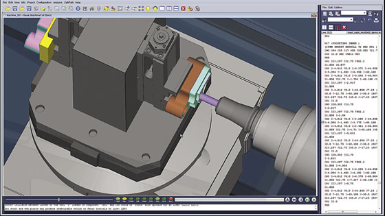
Toolpath simulation of a tombstone-fixtured workpiece on a DMG Mori Seiki horizontal machining center.
The good news is that a number of tooling manufacturers offer CAD files of their products online. Programmers can log into the manufacturer’s Web site, enter a product code and download the file. Not every manufacturer is onboard yet, and it’s possible those CAD models will need some tweaking. And once you have electronic versions of every jaw, clamp, vise, chuck, knob, insert and holder used in the shop, someone in the company has to manage that data. Is all this work really necessary?
Bill Hasenjaeger, product marketing manager for simulation software developer CGTech Inc., Irvine, Calif., thinks it is. “Accurate modeling requires a complete representation of the machine setup,” he said. “Shops with this information catch collisions and tool interference in the programming office. Those who don’t have it discover these problems on the shop floor.”
Despite this, Hasenjaeger indicated that many shops don’t bother with complete modeling until the cost of failure becomes unbearable. When you’ve scrapped a $30,000 workpiece or spent weeks waiting on replacement parts for a crashed machine, a few hours of modeling seems worthwhile. “Those who accurately model toolholders and fixtures as part of program simulation definitely realize a benefit in machine uptime,” Hasenjaeger said.
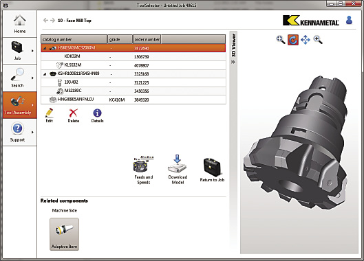
Kennametal’s NOVO is used to view a solid model of a facemill via Machining Cloud.
Fortunately, the days of hand measurements, paper catalogs and endless Internet searches for tooling dimensions and downloadable CAD models may soon be coming to an end. An increasing number of CAD/CAM suppliers—CGTech included—are partnering with tooling manufacturers to make modeling faster and easier.
“Cutting tool manufacturers, in particular, are beginning to realize their customers are using simulation more often, and, therefore, need good tool models,” Hasenjaeger said. CGTech participates in this effort through NOVO, Kenna-metal Inc.’s system for bringing CAD data to the desktop.
Together with Machining Cloud GmbH, NOVO supplies cloud-based tooling information for a number of CAD/CAM systems. According to Hasenjaeger, all that’s required is a few mouse clicks to download and unpack a zip file with the STEP (STandard Exchange of Product data) assemblies necessary to construct the tool and an XML file that contains descriptive information.
Chuck Mathews, business director for Stans, Switzerland-based Machining Cloud, said there’s been a historical disconnect between job shops and tooling suppliers, in that tool data isn’t always readily available. Not only does this make tool and workholding selection difficult, but once the job is tooled up, the data needed to feed the CAM system and CNC isn’t readily available.
Mathews explained that the information needed for part programming and setup is scattered. “Shops end up doing Google searches, checking the manufacturer’s Web site, leafing through paper catalogs and developing in-house databases.” The cloud can be a powerful tool for providing this information, he said.
This isn’t just about downloading the dimensions for a vise or a DXF file for an indexable shell mill. Machining Cloud automates much of the computational work normally done by programmers and engineers, pulling together the various components of a tooling assembly into a complete 3D model.
“In the case of workholding, we prep it using special coordinates so that it can be mounted onto digital machines,” Mathews said. “This eliminates the engineer’s having to find each individual CAD model and fit them all together. We provide a solid model of the complete assembly, formatted to whatever CAD system is being used.”
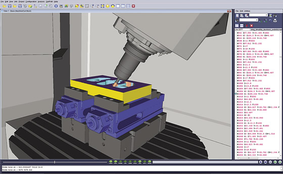
A pair of vises hold a part during 5-axis machining. The part program verification is for a Siemens 840D control.
Kennametal isn’t the only one jumping into the cloud. Machine tool builders, workholder manufacturers and other toolmakers store product data in the cloud, and several CAD/CAM providers are linking to that information (see related article on page 65). One is CNC Software Inc., Tolland, Conn., developer of Mastercam software.
The ability to pull tooling information from the cloud provides a significant advantage to part manufacturers. “One example of this is workholding,” said Steve Bertrand, business manager for CNC Software. “Without an accurate vise or fixture model, about the best you can do is draw an avoidance area on the screen, mapping out the area where tools shouldn’t go.”
This crude representation doesn’t always cut the mustard, though, and operators are often left holding a sweaty hand over the emergency stop button during initial program run-through.
“The nice thing about a solid model is that you can see the details,” Bertrand said. “If the workholder and tooling is drawn to scale, it’s beneficial to programmers because it gives them the information needed to determine the best machining strategy. It makes the job a lot easier and the entire process more efficient.”
Most importantly, it prevents crashes. “I’ve witnessed the results of poor tooling representation. The programmer thought the clamp was over there, and the next thing he knows the operator is standing at his desk because the cutter ran into the fixture,” Bertrand laughed. “Actually, back in the day, I might have caused a few of those situations. I’ve learned since that the more you can show, the better the chances of avoiding a catastrophe.”
Collision detection and avoidance is important, he said, but that’s only half the story. Another key benefit of simulation is determining the best way to position the part.
“Consider a 5-axis application, perhaps a kneecap implant or another complex workpiece,” Bertrand said. “In this case, you want to position the part to minimize the motion of the A and B axes. Good visualization is especially helpful in applications such as these. It tells you the best way to approach the part, how you should hold it and if you’re going to run into trouble with a rotary table or fixture.”
Whether you’re downloading them from the cloud or drawing them from scratch, accurate workholder models are an important part of NC program verification. Fortunately, this tedious job will become easier as the industry continues its efforts to simplify information sharing. In any event, programmers are well advised to avoid shortcuts. Modeling from the workholder up means faster and more predictable machine setups, better process control and no crashes. CTE
About the Author: Kip Hanson is a contributing editor for CTE. Contact him at (520) 548-7328, or [email protected].Related Glossary Terms
- chuck
chuck
Workholding device that affixes to a mill, lathe or drill-press spindle. It holds a tool or workpiece by one end, allowing it to be rotated. May also be fitted to the machine table to hold a workpiece. Two or more adjustable jaws actually hold the tool or part. May be actuated manually, pneumatically, hydraulically or electrically. See collet.
- computer numerical control ( CNC)
computer numerical control ( CNC)
Microprocessor-based controller dedicated to a machine tool that permits the creation or modification of parts. Programmed numerical control activates the machine’s servos and spindle drives and controls the various machining operations. See DNC, direct numerical control; NC, numerical control.
- computer-aided design ( CAD)
computer-aided design ( CAD)
Product-design functions performed with the help of computers and special software.
- computer-aided manufacturing ( CAM)
computer-aided manufacturing ( CAM)
Use of computers to control machining and manufacturing processes.
- facemill
facemill
Milling cutter for cutting flat surfaces.
- feed
feed
Rate of change of position of the tool as a whole, relative to the workpiece while cutting.
- fixture
fixture
Device, often made in-house, that holds a specific workpiece. See jig; modular fixturing.
- machining center
machining center
CNC machine tool capable of drilling, reaming, tapping, milling and boring. Normally comes with an automatic toolchanger. See automatic toolchanger.
- milling machine ( mill)
milling machine ( mill)
Runs endmills and arbor-mounted milling cutters. Features include a head with a spindle that drives the cutters; a column, knee and table that provide motion in the three Cartesian axes; and a base that supports the components and houses the cutting-fluid pump and reservoir. The work is mounted on the table and fed into the rotating cutter or endmill to accomplish the milling steps; vertical milling machines also feed endmills into the work by means of a spindle-mounted quill. Models range from small manual machines to big bed-type and duplex mills. All take one of three basic forms: vertical, horizontal or convertible horizontal/vertical. Vertical machines may be knee-type (the table is mounted on a knee that can be elevated) or bed-type (the table is securely supported and only moves horizontally). In general, horizontal machines are bigger and more powerful, while vertical machines are lighter but more versatile and easier to set up and operate.
- numerical control ( NC)
numerical control ( NC)
Any controlled equipment that allows an operator to program its movement by entering a series of coded numbers and symbols. See CNC, computer numerical control; DNC, direct numerical control.
- process control
process control
Method of monitoring a process. Relates to electronic hardware and instrumentation used in automated process control. See in-process gaging, inspection; SPC, statistical process control.
- solid model
solid model
3-D model created using “building blocks.” This is the most accurate way of representing real-world objects in CAD.
- toolpath( cutter path)
toolpath( cutter path)
2-D or 3-D path generated by program code or a CAM system and followed by tool when machining a part.
- web
web
On a rotating tool, the portion of the tool body that joins the lands. Web is thicker at the shank end, relative to the point end, providing maximum torsional strength.
Author

Kip Hanson is a contributing editor for Cutting Tool Engineering magazine. Contact him by phone at (520) 548-7328 or via e-mail at [email protected].