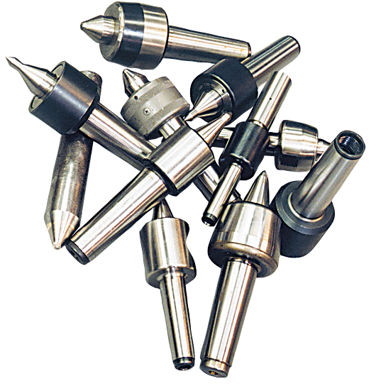
These centers, sent in for repair, were in good working order when originally installed.
Regardless of a live center’s brand, its quality is acceptable or the center manufacturer wouldn’t be in business. In addition, most center designers have kept pace with today’s high-horsepower machines, aggressive machining parameters and high-pressure coolant applications to avoid limiting the accuracy and service life of a live center.
Granting these assumptions, end users should not lay blame for premature failure at the doorstep of the center. After 80 years in the workholding business, and with a department devoted to repairing all makes of centers, Riten Industries understands the main reasons why good centers don’t perform as expected.
Misapplication of a center is probably the most common cause of premature failure. Selecting the right center sounds easy when you know the workpiece weight, the maximum spindle speed, the tailstock taper, required center dimensions, point style for adequate tool clearance and the required accuracy. Catalogs list these specs for each model, so choosing the right center at the best price would seem like a no-brainer.
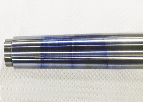
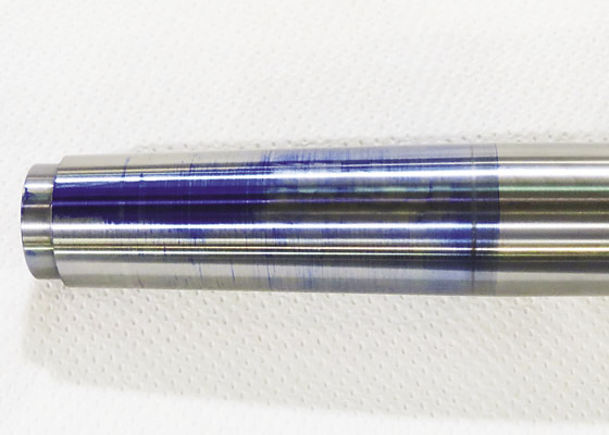
Bluing is a good way to check quill wear. After a blued center taper is inserted into the quill, the bluing should be light and even (top). Heavy bluing indicates the taper did not contact the quill interior, while gaps mean the fit was too tight (bottom).
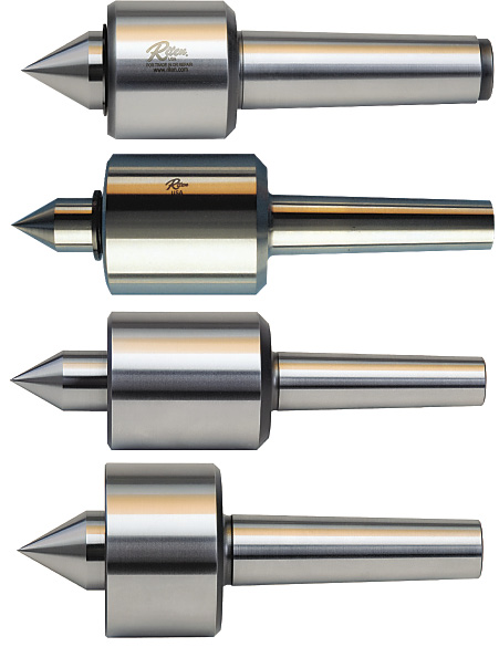
These four Morse Taper live centers have common specs for accuracy, maximum spindle speed and workpiece weight capacity, but users should consult the manufacturer to determine which one is correct for an application.
However, literally thousands of standard and modified centers are available, each designed for specific applications. Center designers select bearing sets, seals and internal lubrication to accommodate varying operating conditions, including the DOC, surface feed and required surface finish. It is always best to consult the center manufacturer about the details of the turning or grinding operation rather than choosing a standard center from a catalog that may not be appropriate for the job.
An incorrect tailstock force ranks a close second when examining the causes of premature center failure. Applying the correct load to the workpiece and center is not an exact science, and often involves guesswork based on experience. Too often, operators guess wrong and tend to overload centers.
The result is excessive force that exceeds the axial load limit of the center bearings, inevitably leading to seizure and early failure. In rare cases, overloading even damages the machine spindle bearings, resulting in costly downtime for replacement and a big repair bill.
Conversely, if the tailstock force is too light, the center will soon slip, chatter and wobble, galling the shaft center hole and damaging the center point. If not shut down quickly, friction-induced heat can weld the center to the workpiece.
There’s no simple formula for determining the correct tailstock force, only suggestions. Make sure the center can handle the part weight, and employ proper machining practices for that weight. For critical applications, buy or rent a special force gage to measure the precise load in pounds of force.
Over time, the tailstock quill, which holds the center, may become out of round and loosen its grip on the center taper. This causes the center to wobble, producing chatter, greatly reduced accuracy and out-of-spec parts.
Quill wear is easy to check. Live and dead center tapers should be manufactured to tolerances much tighter than typical tailstock quill specs, and, therefore, can serve as accurate taper gages. Apply bluing to the center taper and insert it into the quill. Upon removal, if the bluing shows irregularity or gaps, the quill taper requires repair.
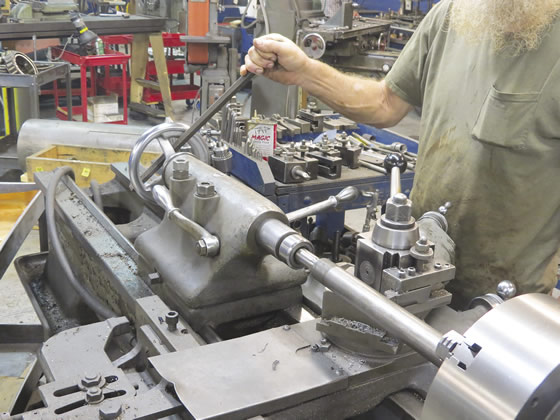
A common practice on manual machines is to manually tighten the tailstock adjustment until the center is snug against the workpiece. This method is often acceptable, provided there is a final firm turn of the wheel by hand—“snug and tug.” A “cheater bar” (pictured), particularly in strong hands, is unnecessary and could generate excessive tailstock force.
Both the cutting tool and center must have sufficient stiffness to avoid deflection under heavy loads. If not, chatter and out-of-round and/or tapered parts result, which can double any subsequent grinding time. Be sure the center has ample capacity and is not running above 60 or 70 percent of its maximum workpiece weight rating. Again, consult the center manufacturer about which model to buy to avoid premature failure and bad parts.
In addition, live center design can include many types of bearing lubrication, depending on the type and severity of the machining operation. Unfortunately, in a misguided attempt to keep a center running longer, operators frequently apply additional lubrication—sometimes in excess. Don’t do this, because the center’s original lubrication may be chemically incompatible with other oils and greases and additional lubrication could cause premature bearing failure.
Workholding is an established rotational science, and manufacturers have experienced technicians who can explain why good centers might behave badly. CTE

Related Glossary Terms
- centers
centers
Cone-shaped pins that support a workpiece by one or two ends during machining. The centers fit into holes drilled in the workpiece ends. Centers that turn with the workpiece are called “live” centers; those that do not are called “dead” centers.
- chatter
chatter
Condition of vibration involving the machine, workpiece and cutting tool. Once this condition arises, it is often self-sustaining until the problem is corrected. Chatter can be identified when lines or grooves appear at regular intervals in the workpiece. These lines or grooves are caused by the teeth of the cutter as they vibrate in and out of the workpiece and their spacing depends on the frequency of vibration.
- clearance
clearance
Space provided behind a tool’s land or relief to prevent rubbing and subsequent premature deterioration of the tool. See land; relief.
- coolant
coolant
Fluid that reduces temperature buildup at the tool/workpiece interface during machining. Normally takes the form of a liquid such as soluble or chemical mixtures (semisynthetic, synthetic) but can be pressurized air or other gas. Because of water’s ability to absorb great quantities of heat, it is widely used as a coolant and vehicle for various cutting compounds, with the water-to-compound ratio varying with the machining task. See cutting fluid; semisynthetic cutting fluid; soluble-oil cutting fluid; synthetic cutting fluid.
- feed
feed
Rate of change of position of the tool as a whole, relative to the workpiece while cutting.
- galling
galling
Condition whereby excessive friction between high spots results in localized welding with subsequent spalling and further roughening of the rubbing surface(s) of one or both of two mating parts.
- grinding
grinding
Machining operation in which material is removed from the workpiece by a powered abrasive wheel, stone, belt, paste, sheet, compound, slurry, etc. Takes various forms: surface grinding (creates flat and/or squared surfaces); cylindrical grinding (for external cylindrical and tapered shapes, fillets, undercuts, etc.); centerless grinding; chamfering; thread and form grinding; tool and cutter grinding; offhand grinding; lapping and polishing (grinding with extremely fine grits to create ultrasmooth surfaces); honing; and disc grinding.
- stiffness
stiffness
1. Ability of a material or part to resist elastic deflection. 2. The rate of stress with respect to strain; the greater the stress required to produce a given strain, the stiffer the material is said to be. See dynamic stiffness; static stiffness.
- turning
turning
Workpiece is held in a chuck, mounted on a face plate or secured between centers and rotated while a cutting tool, normally a single-point tool, is fed into it along its periphery or across its end or face. Takes the form of straight turning (cutting along the periphery of the workpiece); taper turning (creating a taper); step turning (turning different-size diameters on the same work); chamfering (beveling an edge or shoulder); facing (cutting on an end); turning threads (usually external but can be internal); roughing (high-volume metal removal); and finishing (final light cuts). Performed on lathes, turning centers, chucking machines, automatic screw machines and similar machines.