Dear Doc: We cylindrical OD-plunge steel shafts and divide the cycle into the standard rapid-feed, roughing, semifinishing, finishing and spark-out cycles. There’s disagreement about when we should shift from rapid feed to roughing. We don’t have an acoustic emission sensor for first-contact detection. Any thoughts?
The Doc replies: The only way to answer this question is to have some idea of the range of blank diameters going into your grinder. If your shop is like many — maybe most — shops, it doesn’t have a clue and is wasting weeks a year grinding nothing but air.
Let’s say the final diameter after grinding is 25 mm (0.984") and you start roughing at 26 mm (1.024"). Where did that number come from? It’s likely that 26 is just a nice, round number where you’ll know you’ll be safe. Also, back in 1979, a machine operator tried decreasing that to 25.8 mm (1.016") and noticed more wheel wear before going back to 26 mm. And that’s where it’s been ever since.

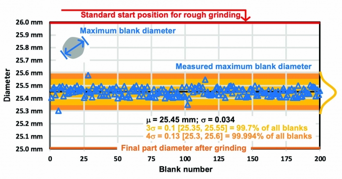
Measure blank diameters on 200 parts to determine when you should switch from rapid feed to rough grinding. Image courtesy of J. Badger
The solution is to measure blank diameters — not just one part or even five parts but perhaps 100 or more. If your part is long, you’ll have to measure cylindricity in addition to diameter.
I once visited a company in Japan that measured 500 blank diameters for every part variation produced. The company then calculated means and standard deviations and thought long and hard about when to shift from rapid feed to roughing. The company was so obsessive because it knew that grinding air was a waste of time and wanted to keep that to a minimum while still ensuring that the wheel didn’t crash into the part.
So, find that engineering intern, give him a micrometer, and tell him to spend three days measuring and plugging the data into a Microsoft Excel spreadsheet. If some batches go into the grinding machine after hard turning and other batches are coming straight from heat treatment, which tends to distort parts, he’ll have to do measurements for both groups. If some parts are 10 mm (0.394") in diameter and some are 100 mm (3.937"), he’ll have to measure those separately. If some parts are long and some are short, he may have to position the parts between centers and measure not diameter but cylindricity to see how length affects distortion.
Once these measurements are completed, the choice of the starting diameter is usually easy. When you do this, you’ll be embarrassed. You’ll think, “Gosh, our largest blank was 25.6 mm (1.008"), and we start rough grinding at 26 mm? That’s absurd.” Don’t tell anybody — just quietly start reprogramming your start diameters.
Is this effort worthwhile? Let’s do some rough calculations. Let’s say your company produces 2 million parts a year and you start roughing from 26 mm in diameter at 2 mm/min. (0.079 ipm) for a respectable Q-prime of 2.6 mm2/sec. (0.24 in.2/min.). If by measuring the blank diameter you can reduce the start diameter from 26 mm to a modest 25.9 mm (1.02"), you’ll save 0.05 mm (0.002") off radius divided by 2 mm/min. = 1.5 seconds per part. That doesn’t seem like much. But at 2 million parts, that’s 3 million seconds, or 833 hours. At, say, $100 an hour, that’s $83,300 a year.
Related Glossary Terms
- centers
centers
Cone-shaped pins that support a workpiece by one or two ends during machining. The centers fit into holes drilled in the workpiece ends. Centers that turn with the workpiece are called “live” centers; those that do not are called “dead” centers.
- feed
feed
Rate of change of position of the tool as a whole, relative to the workpiece while cutting.
- grinding
grinding
Machining operation in which material is removed from the workpiece by a powered abrasive wheel, stone, belt, paste, sheet, compound, slurry, etc. Takes various forms: surface grinding (creates flat and/or squared surfaces); cylindrical grinding (for external cylindrical and tapered shapes, fillets, undercuts, etc.); centerless grinding; chamfering; thread and form grinding; tool and cutter grinding; offhand grinding; lapping and polishing (grinding with extremely fine grits to create ultrasmooth surfaces); honing; and disc grinding.
- grinding machine
grinding machine
Powers a grinding wheel or other abrasive tool for the purpose of removing metal and finishing workpieces to close tolerances. Provides smooth, square, parallel and accurate workpiece surfaces. When ultrasmooth surfaces and finishes on the order of microns are required, lapping and honing machines (precision grinders that run abrasives with extremely fine, uniform grits) are used. In its “finishing” role, the grinder is perhaps the most widely used machine tool. Various styles are available: bench and pedestal grinders for sharpening lathe bits and drills; surface grinders for producing square, parallel, smooth and accurate parts; cylindrical and centerless grinders; center-hole grinders; form grinders; facemill and endmill grinders; gear-cutting grinders; jig grinders; abrasive belt (backstand, swing-frame, belt-roll) grinders; tool and cutter grinders for sharpening and resharpening cutting tools; carbide grinders; hand-held die grinders; and abrasive cutoff saws.
- hard turning
hard turning
Single-point cutting of a workpiece that has a hardness value higher than 45 HRC.
- micrometer
micrometer
A precision instrument with a spindle moved by a finely threaded screw that is used for measuring thickness and short lengths.
- spark-out ( sparking out)
spark-out ( sparking out)
Grinding of a workpiece at the end of a grind cycle without engaging any further down feed. The grinding forces are allowed to subside with time, ensuring a precision surface.
- turning
turning
Workpiece is held in a chuck, mounted on a face plate or secured between centers and rotated while a cutting tool, normally a single-point tool, is fed into it along its periphery or across its end or face. Takes the form of straight turning (cutting along the periphery of the workpiece); taper turning (creating a taper); step turning (turning different-size diameters on the same work); chamfering (beveling an edge or shoulder); facing (cutting on an end); turning threads (usually external but can be internal); roughing (high-volume metal removal); and finishing (final light cuts). Performed on lathes, turning centers, chucking machines, automatic screw machines and similar machines.


