Like ice cream, multiple-spindle machine tools come in an assortment of flavors. The underlining ingredients, however, are enhanced throughput, reduced energy consumption and maximized floor space.
In the minds of some metalworking professionals, multiple-spindle machining conjures up images of massive transfer lines with 40 or more spindles on a head, or 6-spindle automatic screw machines for making huge quantities of the same parts—a capability that continues to diminish in demand. Six-spindle technologies are great at pounding out a lot of parts, but don’t have the flexibility to produce less-than-huge lot sizes and can’t adapt to the pace of part design changes seen in today’s production environment, according to David Fischer, product specialist for Okuma America Corp., Charlotte, N.C.
Okuma offers an array of multiple-spindle alternatives that enable more flexibility. These include twin-spindle vertical and horizontal turning centers with side-by-side spindles and horizontal turning centers with two opposing spindles. “You’re basically machining on one side and then passing it off and machining it on the other side,” Fischer said about the latter. “It may have some oddball secondary operations, but for the most part, you can go to finished part without any operator intervention with dual-spindle capability.”

VIDEO

It’s critical is to properly capacitize a multispindle machine, such as this Chiron DZ08 FX dual-spindle machine. Click here to view video courtesy of Chiron America.
He added that with the side-by-side verticals, most customers run the first operation on one spindle and the second operation on the other after a robot or operator transfers the part. In contrast, the side-by-side horizontal-type lathes come packaged with a parts loader and users either simultaneously run the same operation on both spindles or run separate operations on each spindle. “There’s a lot of flexibility and that’s the whole purpose,” Fischer said. “The customer can decide what suits him best for his production application.”
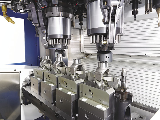
Although the builders of multispindle machine tools typically max out at 4-spindle offerings, Chiron America Inc. did produce a special-purpose 7-spindle configuration for machining injector bodies, explained Norm Holtzhauer, engineering manager for the Charlotte, N.C., company. The tool in the first spindle is for centering, the next two perform predrilling and the remainder simultaneously deep-hole drill four parts.
Automated part load and unload enhances flexibility by enabling users to teach the robot location points for a specific part and then load that set of “teach points” when a job repeats, Fischer noted. Nonetheless, the twin-spindle machines are for relatively high volumes. “There is a lot of flexibility, but you’re not going to run it for onesies or twosies or 10 or 20 parts.”
Suitable Scenarios
SW North America Inc., for example, targets its 2-, 3- and 4-spindle horizontals for production volumes starting at around 250,000 parts per year, according to Matthew Raleigh, application engineer for the machine tool builder. However, he noted if a part has a long cycle time, say 20 minutes, an annual volume of 50,000 parts can be appropriate.
Because of the need for high part volumes, the company targets Tier 1, 2 and even 3 auto suppliers, added James Campbell, vice president of sales for SW North America. The German machine builder opened its Canton, Mich., facility this year to expand business throughout the North American market.
Again, what’s critical is to properly capacitize a multispindle machine. “We have aerospace and medical companies making parts that take 12 to 15 minutes on twin-spindle machines,” Holtzhauer said. “Their volumes are only 20,000 to 30,000 parts, but it takes a whole year to make them.”
A twin-spindle machine with two part nests per spindle is the “sweet spot” and is twice as fast as a single-spindle machine with two nests, he explained. “We call that 2+2. That is the fastest you’re going to be,” he said, adding that Chiron has conducted tests with four to 12 nests. “You can add more parts, depending on the size of your machine and size of your part, but you reach a breakeven point where having to build all the extra nests doesn’t pay for the extra volume you get.”
The four nests are aligned in pairs, and two can be fixed while the other two are movable in the X, Y and Z axes, Holtzhauer added. To enable high part accuracy, the company uses ground shims to adjust the nests and lock them in within microns of each other, with two in the X-axis, one in the Y-axis and three in the Z-axis.
A 4-spindle machine becomes an option when part volume or cycle time dictate that multiple machines would otherwise be required to meet production demands, according to Holtzhauer. This machine would reduce floor space while achieving production goals. Possible applications include deep-hole drilling injector bodies and fuel pumps. “The deep-hole drilling process is slow, so we can have four spindles doing the same process,” he said.
Raleigh noted 4-spindle machines are for parts with tight feature tolerances, such as a brake caliper, but don’t require tight positional tolerances. “On more critical parts, let’s say an aluminum transmission housing, generally we always go with a 2-spindle machine,” he said. Three-spindle machines are for special applications that fall between the volume requirements for a 2- and 4-spindle one.
Step Lightly
In addition, multispindle customers tend to be concerned about floor space. An SW twin-spindle machine can replace three single-spindle machines, according to Campbell. The multispindle unit, even with its heavy monoblock design to minimize deflection, has only a slightly larger footprint than a comparable single-spindle machine while costing about 50 percent more, he added. Most multispindle machines are for new projects and customers want to see how many parts they can produce per square foot while reducing the cost per part. “Nobody wants to add brick and mortar anymore,” Campbell said.
A twin-spindle machine with two part nests per spindle is the “sweet spot” and is twice as fast as a single-spindle machine with two nests, according to Chiron America. Courtesy of Chiron America.
A multispindle machine reduces the cost per part by reducing the required labor, automation and ancillary equipment, Raleigh pointed out. “You don’t have to buy two cooling units, for example, and you don’t need two robots to load and unload it,” he said, noting that one robot or a gantry system is sufficient. “You’re machining two, three or four parts at the same time and making tool changes at the same time. You can amortize those values over two, three or four parts, depending on how many spindles you have.”
A multispindle machine also reduces energy costs compared to a single-spindle machine. For example, generating clean compressed air consumes expensive energy. According to SW, four 1-spindle machines each have a one-position encoder in the X, Y and Z axes, all 12 of which require air for sealing. A 4-spindle machine only needs four (two in the Y-axis) and, therefore, sealing requires 67 percent less compressed air.
“It doesn’t show up on a lot of spreadsheets, but there is a lower energy cost,” Campbell said.
Lightning Fast and Lights Out
To boost throughput by getting complex parts done in one, Eurotech offers double-spindle, double- or triple-turret turn/mill centers with two or three Y axes, said Larry Greenawalt, applications engineering manager for the Brooksville, Fla., machine builder. “You start with raw bar stock coming from a bar feeder through the spindle and complete everything that’s needed on that part.” This can include polygon milling, broaching, spline cutting and drilling angular holes with an articulating B-axis or angular live tools. “Can we produce this part where maybe the customer just has to clean it, put it in a bag and send it out? That’s what we look at first.”
Eurotech’s Clearshift feature enables the subspindle to be offset from the main spindle. This eliminates most interference problems between the two turrets on Trofeo series machines. Both turrets can machine on the main spindle or subspindle. Courtesy of Eurotech.
Greenawalt emphasized the ability of the upper turret to perform ID operations up to about 10 " (254mm) long with the Clearshift subspindle on Eurotech’s Trofeo twin-spindle machines. To eliminate interference between the two turrets, the subspindle shifts down and away from the main spindle centerline instead of having the subspindle in line with the main.
The alternative is to build a machine with an extremely long Z-axis. “You don’t find that many long-bed, 2-turret machines out there,” he said. “But we have that flexibility to shift down and out of the way, so when simultaneous operations are going on you really don’t have any concern over clearance between two turrets trying to share the same space.”
A gantry loader helps the Trofeo machine perform unattended machining, Greenawalt explained. It normally comes down and catches the part coming off the subspindle, but it can also articulate 180° and catch from the main spindle, which is beneficial when handling short bar remnants. Rather than pushing a remnant into the chip pan and letting the conveyor carry it, which might cause it to jam the conveyor or need to be manually separated from the machined chips, the gantry unloader catches the remnant and brings it to the work conveyor that removes parts from the machine. While good parts come out towards the operator, an M code reverses the conveyor to deliver the remnant to the back of the machine.
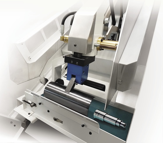
A gantry loader helps the Trofeo machine from Eurotech perform unattended machining. Courtesy of Eurotech.
And while the gantry is catching the part, machining continues on the upper and lower turrets. According to Greenawalt, stopping the machining process to catch a part adds 16 to 18 seconds to cycle time. “In our marketing, we always emphasize speed,” he said. “That’s one small example of where we gain an advantage.”
Although 25 percent of Eurotech’s sales effort targets part manufacturers already familiar with multispindle turn/mill centers, Greenawalt noted the remainder is geared towards presenting an alternative to users focused on using work cells. Such a cell might include a 2-axis lathe, a 3-axis VMC and a parts washer. “Our concept is to make the part complete and run 24/7 unattended, and we have customers doing that.”
A 6-spindle screw machine is another option for quickly producing complex parts, but the price can start at $1 million. The flexibility of multiple-spindle and -turret machines, such as putting more than one tool on one turret station, makes the lower-cost, dual-spindle equipment suitable even for job shops, Greenawalt said. “We have a tool called Quad ID Block, where we can put eight ID tools on one station: four out the front and four out the back. That concept is used by a lot of contract shops to reduce setup.”
Setup can also be reduced by machining different parts from the same bar stock diameter, such as 13/8" (34.9mm), even when the maximum feature is only 1 " (25.4mm) in diameter. “It’s almost a wash as far as the extra cost to run 13/8" versus 1 ",” Greenawalt said. “As fast as an operator can change over to the next program is the setup time. We’re talking 1 to 2 minutes.”
K.I.S.S.
Okuma’s Fischer emphasized that a priority when designing a twin-spindle machine is to keep it simple for the operator and programmer. When programming a specific turret/spindle combination, such as upper turret with left spindle or lower turret with right spindle, they are programmed as if they were upper turret with left spindle. “The Okuma OSP control flips the geometry based on the actual turret/spindle combination,” he said.
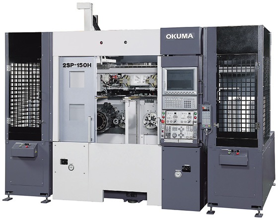
Okuma's 2SP-150H machine has two spidles positioned side by side. Courtesy of Okuma America.
So if an end user wants to run a fea ture on the lower turret instead of the upper, Fischer continued, he simply changes the G code and it will run on the lower turret. “What’s nice is the programmer doesn’t have to change his way of thinking whether he’s on the upper turret, lower turret, left spindle or right spindle.”
If the programmer wants to change the process and do an operation on the right spindle instead of the left one to provide a better balance, for example, he doesn’t have to recode the whole process. “He can just flip the G code and change it to the right spindle,” Fischer said. “The geometry stays the same inside the program. We use one program for both turrets.”
This makes file management less cumbersome. Instead of having, say, 1,500 files for 500 programs on a 3-turret machine, a user has just 500 files, Fischer said. “The operator has to load one program correctly, not two or three.”
While a multiple-spindle machine tool isn’t a good fit for everyone, the consequences can be significant when it is. “If you get left behind on the technology, you put your business at risk,” Fischer warned.
Nonetheless, getting the first multiple-spindle machine in an appropriate plant can be a challenge. SW North America’s Campbell said having a spindle fail is a primary concern among prospects. To make them more comfortable with the technology, he provides information about the low failure rate for its spindles and the builder’s ability to quickly replace a spindle should one fail. “The spindles are very seldom a problem,” he added.
A 4-spindle machine, such as this Chiron TZ12 W, is an option when part volume or cycle time dictate that multiple machines would otherwise be required to meet production demands. Courtesy of Chiron America.
After customers realize the benefits with one, repeat sales are a breeze. “I would say 60 to 75 percent of our sales are from repeat customers,” Campbell said, “which is really what it’s all about.”
And one multispindle benefit trumps all others. The machines cost about 35 percent more than the company’s single-spindle machine, said Chiron’s Holtzhauer, “but you’re basically getting double the output, so you are going to see a nice drop in the cost per part.”

A different shade of multiple spindle
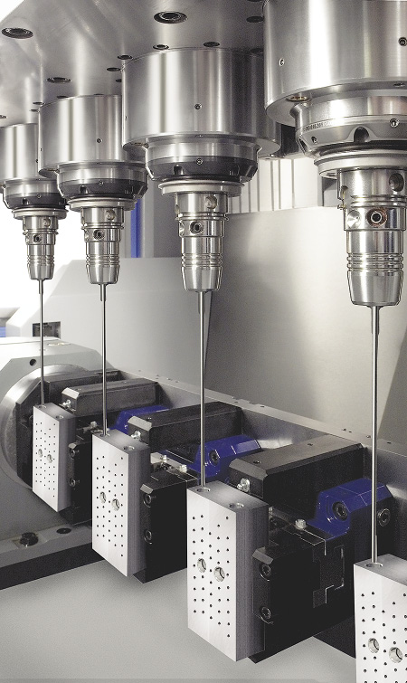
Some multiple-spindle machine tools are cutting-tool-intensive. The Cyclone 70 3TMY twin-spindle, 3-turret CNC turn/mill screw machine from Ganesh Machinery, for example, has 16 tool positions on each turret for a total of 48 positions. Each tool position can support multiple cutting tools from the front and back of the toolholder, and, with the Y-axis, users can mount up to four turning tools in one tool station. In addition, employing boring bars with dual inserts enhances the tool count. This enables the machine to have 80 or more tools, depending on the application, explained Kamal Grewal, who handles marketing for the Chatsworth, Calif., machine tool builder.
He added that the machine, which has a bar capacity of 71mm (2.75 "), performs simultaneous front and back work to get a part done in one chucking. “It’s a combined turning and milling operation.”
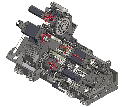
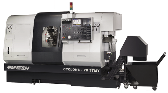
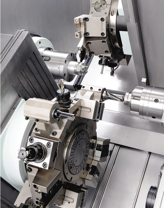
The Cyclone 70 3TMY from Ganesh Machinery is a twin-spindle mill/turn machine with two Y-axis tool turrets in the upper position and a 2-axis tool turret on the lower slideway. Courtesy of Ganesh Machinery.
According to the company, a machine tooled up to that level allows multiple jobs to be set up on the machine at once, so an operator can go from job to job without needing a setup man.
Using a tool life management system, an ample number of tools also lets a shop apply a redundant tool rather than replace a tool when it wears out. This is particularly beneficial when running unattended, noted Jeff Jessop, an application engineer for Ganesh.
“Each of those tool positions has live tool capability as well,” Jessop said. “If you want to use live tooling or standard dead tooling to perform deburring, for example, you can do that in the machine.”
This arrangement allows the machine to do the deburring rather than a low-skilled worker, who might scrap a nearly finished part during manual deburring.
The 11-axis machine has a solid headstock, so it doesn’t have a guide bushing, and requires users to think outside of the box. “You’re looking at a machine where, typically speaking, you have three tools in the cut on two parts at one time,” Jessop said. “It’s not something you think conventionally about. You have to think about what all your possibilities are and how you can utilize them.”
—A. Richter
Contributors
Chiron America Inc.
(704) 587-9526
www.chironamerica.com
Eurotech
(352) 799-5223
www.eurotechelite.com
Ganesh Machinery
(888) 542-6374
www.ganeshmachinery.com
Okuma America Corp.
(704) 588-7000
www.okuma.com
SW North America Inc.
(248) 622-9725
www.sw-machines.com
Related Glossary Terms
- boring
boring
Enlarging a hole that already has been drilled or cored. Generally, it is an operation of truing the previously drilled hole with a single-point, lathe-type tool. Boring is essentially internal turning, in that usually a single-point cutting tool forms the internal shape. Some tools are available with two cutting edges to balance cutting forces.
- broaching
broaching
Operation in which a cutter progressively enlarges a slot or hole or shapes a workpiece exterior. Low teeth start the cut, intermediate teeth remove the majority of the material and high teeth finish the task. Broaching can be a one-step operation, as opposed to milling and slotting, which require repeated passes. Typically, however, broaching also involves multiple passes.
- bushing
bushing
Cylindrical sleeve, typically made from high-grade tool steel, inserted into a jig fixture to guide cutting tools. There are three main types: renewable, used in liners that in turn are installed in the jig; press-fit, installed directly in the jig for short production runs; and liner (or master), installed permanently in a jig to receive renewable bushing.
- centering
centering
1. Process of locating the center of a workpiece to be mounted on centers. 2. Process of mounting the workpiece concentric to the machine spindle. See centers.
- centers
centers
Cone-shaped pins that support a workpiece by one or two ends during machining. The centers fit into holes drilled in the workpiece ends. Centers that turn with the workpiece are called “live” centers; those that do not are called “dead” centers.
- clearance
clearance
Space provided behind a tool’s land or relief to prevent rubbing and subsequent premature deterioration of the tool. See land; relief.
- computer numerical control ( CNC)
computer numerical control ( CNC)
Microprocessor-based controller dedicated to a machine tool that permits the creation or modification of parts. Programmed numerical control activates the machine’s servos and spindle drives and controls the various machining operations. See DNC, direct numerical control; NC, numerical control.
- gang cutting ( milling)
gang cutting ( milling)
Machining with several cutters mounted on a single arbor, generally for simultaneous cutting.
- inner diameter ( ID)
inner diameter ( ID)
Dimension that defines the inside diameter of a cavity or hole. See OD, outer diameter.
- lathe
lathe
Turning machine capable of sawing, milling, grinding, gear-cutting, drilling, reaming, boring, threading, facing, chamfering, grooving, knurling, spinning, parting, necking, taper-cutting, and cam- and eccentric-cutting, as well as step- and straight-turning. Comes in a variety of forms, ranging from manual to semiautomatic to fully automatic, with major types being engine lathes, turning and contouring lathes, turret lathes and numerical-control lathes. The engine lathe consists of a headstock and spindle, tailstock, bed, carriage (complete with apron) and cross slides. Features include gear- (speed) and feed-selector levers, toolpost, compound rest, lead screw and reversing lead screw, threading dial and rapid-traverse lever. Special lathe types include through-the-spindle, camshaft and crankshaft, brake drum and rotor, spinning and gun-barrel machines. Toolroom and bench lathes are used for precision work; the former for tool-and-die work and similar tasks, the latter for small workpieces (instruments, watches), normally without a power feed. Models are typically designated according to their “swing,” or the largest-diameter workpiece that can be rotated; bed length, or the distance between centers; and horsepower generated. See turning machine.
- metalworking
metalworking
Any manufacturing process in which metal is processed or machined such that the workpiece is given a new shape. Broadly defined, the term includes processes such as design and layout, heat-treating, material handling and inspection.
- milling
milling
Machining operation in which metal or other material is removed by applying power to a rotating cutter. In vertical milling, the cutting tool is mounted vertically on the spindle. In horizontal milling, the cutting tool is mounted horizontally, either directly on the spindle or on an arbor. Horizontal milling is further broken down into conventional milling, where the cutter rotates opposite the direction of feed, or “up” into the workpiece; and climb milling, where the cutter rotates in the direction of feed, or “down” into the workpiece. Milling operations include plane or surface milling, endmilling, facemilling, angle milling, form milling and profiling.
- toolholder
toolholder
Secures a cutting tool during a machining operation. Basic types include block, cartridge, chuck, collet, fixed, modular, quick-change and rotating.
- turning
turning
Workpiece is held in a chuck, mounted on a face plate or secured between centers and rotated while a cutting tool, normally a single-point tool, is fed into it along its periphery or across its end or face. Takes the form of straight turning (cutting along the periphery of the workpiece); taper turning (creating a taper); step turning (turning different-size diameters on the same work); chamfering (beveling an edge or shoulder); facing (cutting on an end); turning threads (usually external but can be internal); roughing (high-volume metal removal); and finishing (final light cuts). Performed on lathes, turning centers, chucking machines, automatic screw machines and similar machines.
Author

Alan holds a bachelor’s degree in journalism from Southern Illinois University Carbondale. Including his 20 years at CTE, Alan has more than 30 years of trade journalism experience.