Understanding cutting equations

Author Christopher Tate
Published
July 01, 2014 - 10:30am

Surface feet per minute, chip load, undeformed chip thickness and chip thinning are familiar shop terms. Over the last few weeks, however, several occurrences in our shop have made me realize there are a lot of metalworking professionals who don’t understand these terms and the calculations that go along with them. Whether you work at a small job shop or a large contract manufacturer, it is important to understand cutting tool calculations and how to use them to help drive significant efficiency gains.

Cutting speed calculations might well be the most important ones. They are easy to use and, with a little explanation, easy to understand. The cutting speed of a tool is expressed in surface feet per minute (sfm) or surface meters per minute (m/min.). Similar to mph for a car, sfm is the linear distance a cutting tool travels per minute. To get a better sense of scale, 300 sfm, for example, converts to 3.4 mph.

Toolmakers recommend cutting speeds for different types of workpiece materials. When a toolmaker suggests 100 sfm, it is indicating the outside surface of the rotating tool should travel at a rate of speed equal to 100 linear feet per minute. If the tool has a circumference (diameter × π) of 12", it would need to rotate at 100 rpm to achieve 100 sfm.

Toolmakers recommend cutting speeds for different types of workpiece materials. Image courtesy of Christopher Tate.

All images courtesy C. Tate

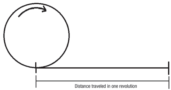
Imagine the cutting tool as a rolling ring or cylinder. The distance traveled in one revolution times rpm is its surface speed. If the circle above had a diameter of 3.82", the circumference would be 12". As a result, every revolution would produce a linear distance of 1', and a spindle speed of 100 rpm would be a cutting speed of 100 sfm.

The following equation is used to calculate spindle speed: rpm = sfm ÷ diameter × 3.82, where diameter is the cutting tool diameter or the part diameter on a lathe in inches, and 3.82 is a constant that comes from an algebraic simplifica-tion of the more complex formula: rpm = (sfm × 12) ÷ (diameter × π).

You can play around with this formula in this simple Online Calculator

Because the tool diameter is measured in inches, the “feet” in sfm must be converted to inches, and because there are 12 inches in a foot, multiply sfm by 12. In addition, the circumference of the tool is found by multiplying the tool diameter by π, or 3.14 to simplify. The result is: rpm = (sfm × 12) ÷ (diameter × π) = (sfm ÷ diameter) × (12 ÷ π) = (sfm ÷ diameter) × 3.82.

Understanding these relationships and applying some creative thought can provide significant gains in efficiency. Image courtesy of Christopher Tate.

Notice the vertical lines, called tool marks, on the outside of the part being turned. As the feed rate increases, the distance between the lines also increases. The chip thickness is roughly equal to the feed.

Cutting speeds are published in sfm because the ideal cutting speed for a particular family of tools will, in theory, be the same no matter the size of the tool. The engineer, programmer or machinist is expected to calculate the rpm needed to produce the proper cutting speed for each selected tool.

So what is this telling us? Let’s say a 1"-dia. tool must run at 100 sfm. Based on the equation, that tool must turn at 382 rpm to achieve 100 sfm: 100 ÷ 1 × 3.82 = 382.

Another way to consider this concept is to think about the distance the 1" tool would travel were it to make 382 revolutions across the shop floor. In that scenario, it would travel 100'; do it in 60 seconds and it would be traveling 100 sfm.

Lathes are different, of course, because the workpiece rotates instead of the cutter. Because the formula for cutting speed is dependent on diameter, as the diameter of the workpiece decreases, rpm must increase to maintain a constant surface speed. After each circular cut on the lathe, the workpiece OD decreases or the ID increases, and it is necessary for the rpm of the part to increase to maintain the desired cutting speed. As a result, CNC manufacturers developed the constant surface footage feature for lathe controls. This feature allows the programmer to input the desired cutting speed in sfm or m/min. and the control calculates the proper rpm for the changing diameter.

While the tool or part is spinning, the machine must know how fast to travel while the cutter is engaged in the workpiece. Feed rate is the term that describes the traverse rate while cutting.

Feed rate for milling is usually expressed in inches per minute (ipm) and calculated using: ipm = rpm × no. of flutes × chip load.

What is chip load? When milling, it is the amount of material that the cutting edge removes each time it rotates. When turning, it is the distance the part moves in one revolution while engaged with the tool. It is sometimes referred to as chip thickness, which is sort of true. Chip thickness can change when other parameters like radial DOC or the tool’s lead angle change.

Toolmakers publish chip load recommendations along with cutting speed recommendations and express them in thousandths of an inch (millimeter for metric units). For milling and drilling operations, chip load is expressed in thousandths of an inch per flute. Flutes, teeth and cutting edges all describe the same thing and there must be at least one, but, in theory, there is no limit to the number a tool can have.

Chip load recommendations for turning operations are most often given in thousandths of an inch per revolution, or feed per rev. This is the distance the tool advances each time the part com-pletes one rotation.

What rpm and feed rate should be programmed for a 4-flute, 1" endmill, running at a recommended cutting speed of 350 sfm and a recommended chip load of 0.005 inch per tooth (ipt)? Using the equation, rpm = sfm ÷ diameter × 3.82 = 350 ÷ 1.0 × 3.82 = 1,337, the feed rate = rpm × no. of flutes × chip load = 1,337 × 4 × 0.005 = 26.74 ipm.

Here is where things get interesting, because by changing the values in the formula, the relationships of the different variables become evident. Try applying a 2" tool instead of the 1" tool. What happens? The rpm and feed rate decrease by half.

Understanding these relationships and applying some creative thought can provide significant gains in efficiency. I will discuss how to take advantage of these relationships in my next column. CTE

About the Author: Christopher Tate is senior advanced manufacturing engineering for Milwaukee Electric Tool Corp., Brookfield, Wis. He is based at the company’s manufacturing plant in Jackson, Miss. He has 19 years of experience in the metalworking industry and holds a Master of Science and Bachelor of Science from Mississippi State University. E-mail: chris23tate@gmail.com.

Related Glossary Terms

  • computer numerical control ( CNC)

    computer numerical control ( CNC)

    Microprocessor-based controller dedicated to a machine tool that permits the creation or modification of parts. Programmed numerical control activates the machine’s servos and spindle drives and controls the various machining operations. See DNC, direct numerical control; NC, numerical control.

  • cutting speed

    cutting speed

    Tangential velocity on the surface of the tool or workpiece at the cutting interface. The formula for cutting speed (sfm) is tool diameter 5 0.26 5 spindle speed (rpm). The formula for feed per tooth (fpt) is table feed (ipm)/number of flutes/spindle speed (rpm). The formula for spindle speed (rpm) is cutting speed (sfm) 5 3.82/tool diameter. The formula for table feed (ipm) is feed per tooth (ftp) 5 number of tool flutes 5 spindle speed (rpm).

  • endmill

    endmill

    Milling cutter held by its shank that cuts on its periphery and, if so configured, on its free end. Takes a variety of shapes (single- and double-end, roughing, ballnose and cup-end) and sizes (stub, medium, long and extra-long). Also comes with differing numbers of flutes.

  • feed

    feed

    Rate of change of position of the tool as a whole, relative to the workpiece while cutting.

  • flutes

    flutes

    Grooves and spaces in the body of a tool that permit chip removal from, and cutting-fluid application to, the point of cut.

  • gang cutting ( milling)

    gang cutting ( milling)

    Machining with several cutters mounted on a single arbor, generally for simultaneous cutting.

  • inches per minute ( ipm)

    inches per minute ( ipm)

    Value that refers to how far the workpiece or cutter advances linearly in 1 minute, defined as: ipm = ipt 5 number of effective teeth 5 rpm. Also known as the table feed or machine feed.

  • inches per minute ( ipm)2

    inches per minute ( ipm)

    Value that refers to how far the workpiece or cutter advances linearly in 1 minute, defined as: ipm = ipt 5 number of effective teeth 5 rpm. Also known as the table feed or machine feed.

  • inner diameter ( ID)

    inner diameter ( ID)

    Dimension that defines the inside diameter of a cavity or hole. See OD, outer diameter.

  • lathe

    lathe

    Turning machine capable of sawing, milling, grinding, gear-cutting, drilling, reaming, boring, threading, facing, chamfering, grooving, knurling, spinning, parting, necking, taper-cutting, and cam- and eccentric-cutting, as well as step- and straight-turning. Comes in a variety of forms, ranging from manual to semiautomatic to fully automatic, with major types being engine lathes, turning and contouring lathes, turret lathes and numerical-control lathes. The engine lathe consists of a headstock and spindle, tailstock, bed, carriage (complete with apron) and cross slides. Features include gear- (speed) and feed-selector levers, toolpost, compound rest, lead screw and reversing lead screw, threading dial and rapid-traverse lever. Special lathe types include through-the-spindle, camshaft and crankshaft, brake drum and rotor, spinning and gun-barrel machines. Toolroom and bench lathes are used for precision work; the former for tool-and-die work and similar tasks, the latter for small workpieces (instruments, watches), normally without a power feed. Models are typically designated according to their “swing,” or the largest-diameter workpiece that can be rotated; bed length, or the distance between centers; and horsepower generated. See turning machine.

  • lead angle

    lead angle

    Angle between the side-cutting edge and the projected side of the tool shank or holder, which leads the cutting tool into the workpiece.

  • metalworking

    metalworking

    Any manufacturing process in which metal is processed or machined such that the workpiece is given a new shape. Broadly defined, the term includes processes such as design and layout, heat-treating, material handling and inspection.

  • milling

    milling

    Machining operation in which metal or other material is removed by applying power to a rotating cutter. In vertical milling, the cutting tool is mounted vertically on the spindle. In horizontal milling, the cutting tool is mounted horizontally, either directly on the spindle or on an arbor. Horizontal milling is further broken down into conventional milling, where the cutter rotates opposite the direction of feed, or “up” into the workpiece; and climb milling, where the cutter rotates in the direction of feed, or “down” into the workpiece. Milling operations include plane or surface milling, endmilling, facemilling, angle milling, form milling and profiling.

  • outer diameter ( OD)

    outer diameter ( OD)

    Dimension that defines the exterior diameter of a cylindrical or round part. See ID, inner diameter.

  • turning

    turning

    Workpiece is held in a chuck, mounted on a face plate or secured between centers and rotated while a cutting tool, normally a single-point tool, is fed into it along its periphery or across its end or face. Takes the form of straight turning (cutting along the periphery of the workpiece); taper turning (creating a taper); step turning (turning different-size diameters on the same work); chamfering (beveling an edge or shoulder); facing (cutting on an end); turning threads (usually external but can be internal); roughing (high-volume metal removal); and finishing (final light cuts). Performed on lathes, turning centers, chucking machines, automatic screw machines and similar machines.