Making money at a small shop often means taking jobs that do not fit the exact capacity or capability of the available machines. Creativity and adaptation are critical to solving issues that arise when you need to do something with a machine that it was not necessarily intended to do.
At my family’s shop, creativity and improvisation were frequently required when operating CNC lathes—more so than other machines. Customers would need help with critical parts, and—feeling obliged to take paying jobs—we would accept their challenging jobs.
Turning centers come in two configurations: bar machines and chucker machines. Chucker machines are designed to have single parts loaded into a chuck, whereas bar machines are set up to make multiple parts from bar stock, eliminating the need to continuously load workpieces. Bar machines are typically outfitted with devices like bar feeders, bar pullers, parts catchers and collet chucks, which enable bar machines to efficiently make parts in a continuous manner.
Creative Cutting
Machines at our shop were purchased as chucker machines, the most common configuration. Our machines had no provisions for doing bar work. However, we often accepted jobs more suitable for bar machines, which forced us to be creative.
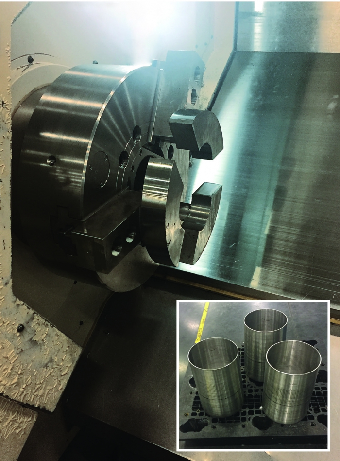
These thin shells (inset) were once trimmed by hand, which was unsafe and inaccurate. Welders and machinists at Mitsubishi Hitachi Power Systems developed a special set of jaws so the parts could be held on a lathe, eliminating hand trimming. All images: C. Tate.
Continuous operation without a machinist present is the primary benefit of running parts from bar stock. As each part’s features are machined, the part is parted, or cut off, from the bar. At that point, the bar must be advanced so the next part can be made. Some lathes are fitted with a bar feeder that, when commanded, will drive the bar forward to the correct position so the cycle can run again.
A less expensive and common substitute for a bar feeder is a bar puller. Bar pullers are mounted in a spare tool position and grip the end of the cut bar while the turret pulls the bar into position.
To continuously operate while being frugal, we made our own bar puller. It worked so well pulling became our standard method for bar work.
A bar puller can be easily made from a piece of tool steel by boring a hole the same size as the bar stock so there’s a slight interference fit. The depth should be about twice the bore diameter. Turn the OD so the wall thickness is about 0.125" (3.175mm). Next, mill or saw axial grooves in the wall so the puller has four independent “fingers” that can flex as it pushes onto a bar. If the puller is not tight enough, simply bend in the fingers a little to increase the interference between the bar and puller ID.
Whether using a feeder or puller, cutoff parts will fall. Machines are often outfitted with part catchers that retrieve and deposit parts so the machine can continuously run. Not having a part catcher meant parts cut off by our machine would fall into the bottom of the machine, making them subject to loss or damage. We found a simple, effective way to catch parts by placing a plastic bar in the tailstock.
When a part was cut off, the tailstock would move forward and place the plastic in the ID of the part, catch it after cutoff and then retract as the operation continued. While not as efficient as a part catcher installed by the machine tool builder, it was effective. Of course, this method has drawbacks. You can’t catch parts that do not have holes, and it is necessary to stop the machine to retrieve the parts.
Casting Ploy
Another trick we learned was how to hold irregularly shaped parts in a 3-jaw chuck. We machined a lot of castings, many of which had features that were best when turned. However, many of these castings were not easily held in chucks or collets because they were asymmetric, unlike the round, hex or square shapes often found in turning operations.
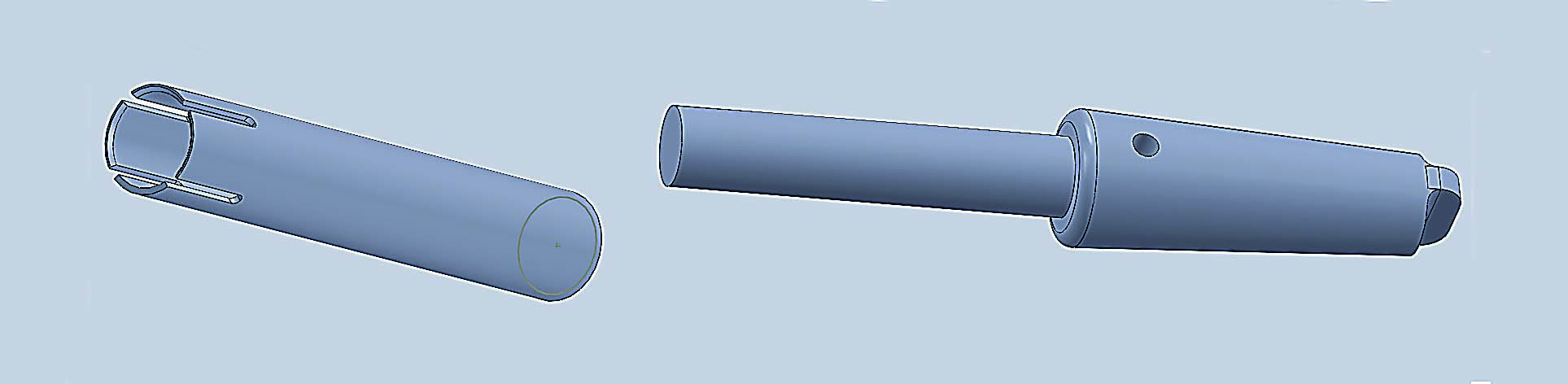
Bar pullers (left) are mounted in a spare tool position and grip the end of the cut bar while the turret pulls the bar into position. This Morse taper adapter (right) fit into a tailstock and held rods, which would catch parts. Rods of varying diameters could be installed and held in place with a setscrew.
The solution was to make a special set of chuck jaws for the 3-jaw chuck. Machining jaws for a CNC lathe is necessary and common at most shops. Most of the time, these jaws are made for round parts by boring or turning on the lathe where the work will be performed.
Many of the castings we machined were not round, so turning a set of jaws on the lathe would not work. To overcome the problem, we built a fixture for the mill that allowed us to machine odd shapes into jaw blanks. After milling, the jaws were installed on the lathe chuck, allowing us to create features that were best made by turning. The only issue with this method comes when runout is critical. Accuracy is lost when the jaws are transferred from a mill to a lathe, so this method may not be suitable for parts with tight runout tolerances.
In ideal situations, a shop will always have the best tools and methods to perform a specific job. However, at many shops, workpieces vary in geometry and size, making flexibility critical to survival. Combine variation and financial constraints, and success often can seem out of reach.
Succeeding in a competitive market requires toolmakers, machinists, shop owners and engineers to be creative and imaginative. I have found that taking advantage of trade shows, joining industrial organizations, touring other facilities and reading trade literature are some of the best ways to get the creative juices flowing.
Most importantly, encourage the people at your shop to be creative and try new ideas without fear of failure.
Related Glossary Terms
- boring
boring
Enlarging a hole that already has been drilled or cored. Generally, it is an operation of truing the previously drilled hole with a single-point, lathe-type tool. Boring is essentially internal turning, in that usually a single-point cutting tool forms the internal shape. Some tools are available with two cutting edges to balance cutting forces.
- centers
centers
Cone-shaped pins that support a workpiece by one or two ends during machining. The centers fit into holes drilled in the workpiece ends. Centers that turn with the workpiece are called “live” centers; those that do not are called “dead” centers.
- chuck
chuck
Workholding device that affixes to a mill, lathe or drill-press spindle. It holds a tool or workpiece by one end, allowing it to be rotated. May also be fitted to the machine table to hold a workpiece. Two or more adjustable jaws actually hold the tool or part. May be actuated manually, pneumatically, hydraulically or electrically. See collet.
- collet
collet
Flexible-sided device that secures a tool or workpiece. Similar in function to a chuck, but can accommodate only a narrow size range. Typically provides greater gripping force and precision than a chuck. See chuck.
- computer numerical control ( CNC)
computer numerical control ( CNC)
Microprocessor-based controller dedicated to a machine tool that permits the creation or modification of parts. Programmed numerical control activates the machine’s servos and spindle drives and controls the various machining operations. See DNC, direct numerical control; NC, numerical control.
- cutoff
cutoff
Step that prepares a slug, blank or other workpiece for machining or other processing by separating it from the original stock. Performed on lathes, chucking machines, automatic screw machines and other turning machines. Also performed on milling machines, machining centers with slitting saws and sawing machines with cold (circular) saws, hacksaws, bandsaws or abrasive cutoff saws. See saw, sawing machine; turning.
- fixture
fixture
Device, often made in-house, that holds a specific workpiece. See jig; modular fixturing.
- gang cutting ( milling)
gang cutting ( milling)
Machining with several cutters mounted on a single arbor, generally for simultaneous cutting.
- inner diameter ( ID)
inner diameter ( ID)
Dimension that defines the inside diameter of a cavity or hole. See OD, outer diameter.
- lathe
lathe
Turning machine capable of sawing, milling, grinding, gear-cutting, drilling, reaming, boring, threading, facing, chamfering, grooving, knurling, spinning, parting, necking, taper-cutting, and cam- and eccentric-cutting, as well as step- and straight-turning. Comes in a variety of forms, ranging from manual to semiautomatic to fully automatic, with major types being engine lathes, turning and contouring lathes, turret lathes and numerical-control lathes. The engine lathe consists of a headstock and spindle, tailstock, bed, carriage (complete with apron) and cross slides. Features include gear- (speed) and feed-selector levers, toolpost, compound rest, lead screw and reversing lead screw, threading dial and rapid-traverse lever. Special lathe types include through-the-spindle, camshaft and crankshaft, brake drum and rotor, spinning and gun-barrel machines. Toolroom and bench lathes are used for precision work; the former for tool-and-die work and similar tasks, the latter for small workpieces (instruments, watches), normally without a power feed. Models are typically designated according to their “swing,” or the largest-diameter workpiece that can be rotated; bed length, or the distance between centers; and horsepower generated. See turning machine.
- milling
milling
Machining operation in which metal or other material is removed by applying power to a rotating cutter. In vertical milling, the cutting tool is mounted vertically on the spindle. In horizontal milling, the cutting tool is mounted horizontally, either directly on the spindle or on an arbor. Horizontal milling is further broken down into conventional milling, where the cutter rotates opposite the direction of feed, or “up” into the workpiece; and climb milling, where the cutter rotates in the direction of feed, or “down” into the workpiece. Milling operations include plane or surface milling, endmilling, facemilling, angle milling, form milling and profiling.
- milling machine ( mill)
milling machine ( mill)
Runs endmills and arbor-mounted milling cutters. Features include a head with a spindle that drives the cutters; a column, knee and table that provide motion in the three Cartesian axes; and a base that supports the components and houses the cutting-fluid pump and reservoir. The work is mounted on the table and fed into the rotating cutter or endmill to accomplish the milling steps; vertical milling machines also feed endmills into the work by means of a spindle-mounted quill. Models range from small manual machines to big bed-type and duplex mills. All take one of three basic forms: vertical, horizontal or convertible horizontal/vertical. Vertical machines may be knee-type (the table is mounted on a knee that can be elevated) or bed-type (the table is securely supported and only moves horizontally). In general, horizontal machines are bigger and more powerful, while vertical machines are lighter but more versatile and easier to set up and operate.
- outer diameter ( OD)
outer diameter ( OD)
Dimension that defines the exterior diameter of a cylindrical or round part. See ID, inner diameter.
- sawing machine ( saw)
sawing machine ( saw)
Machine designed to use a serrated-tooth blade to cut metal or other material. Comes in a wide variety of styles but takes one of four basic forms: hacksaw (a simple, rugged machine that uses a reciprocating motion to part metal or other material); cold or circular saw (powers a circular blade that cuts structural materials); bandsaw (runs an endless band; the two basic types are cutoff and contour band machines, which cut intricate contours and shapes); and abrasive cutoff saw (similar in appearance to the cold saw, but uses an abrasive disc that rotates at high speeds rather than a blade with serrated teeth).
- turning
turning
Workpiece is held in a chuck, mounted on a face plate or secured between centers and rotated while a cutting tool, normally a single-point tool, is fed into it along its periphery or across its end or face. Takes the form of straight turning (cutting along the periphery of the workpiece); taper turning (creating a taper); step turning (turning different-size diameters on the same work); chamfering (beveling an edge or shoulder); facing (cutting on an end); turning threads (usually external but can be internal); roughing (high-volume metal removal); and finishing (final light cuts). Performed on lathes, turning centers, chucking machines, automatic screw machines and similar machines.
Author

Christopher Tate is the owner of Tate Engineering, a Natchez, Mississippi, firm that helps manufacturers solve efficiency problems. Tate, who earned master's degree in industrial technology from Mississippi State University, has 32 years of experience in the metalworking industry.