Turning catching up in the use of chip thinning
Milling operations that benefit from chip thinning have become common, now it's turning's time.
High-speed machining, high-feed milling and high-efficiency milling are terms that have been incorporated into the modern machining lexicon. While nuances make their meanings slightly different—depending on whom you ask—all the techniques take advantage of radial and axial chip thinning.
Cutting tool manufacturers have been designing milling tools to exploit chip thinning while machine tool builders have been creating more dynamic milling machines that allow users to capitalize on the advanced tools.
As a result, milling operations that benefit from chip thinning have become common at many shops.
Turning operations that employ chip thinning have been slower to advance than milling operations. This lag is odd. After all, the chip morphology research that initially defined the characteristics of chip thinning was performed using orthogonal machining operations like turning and planing.
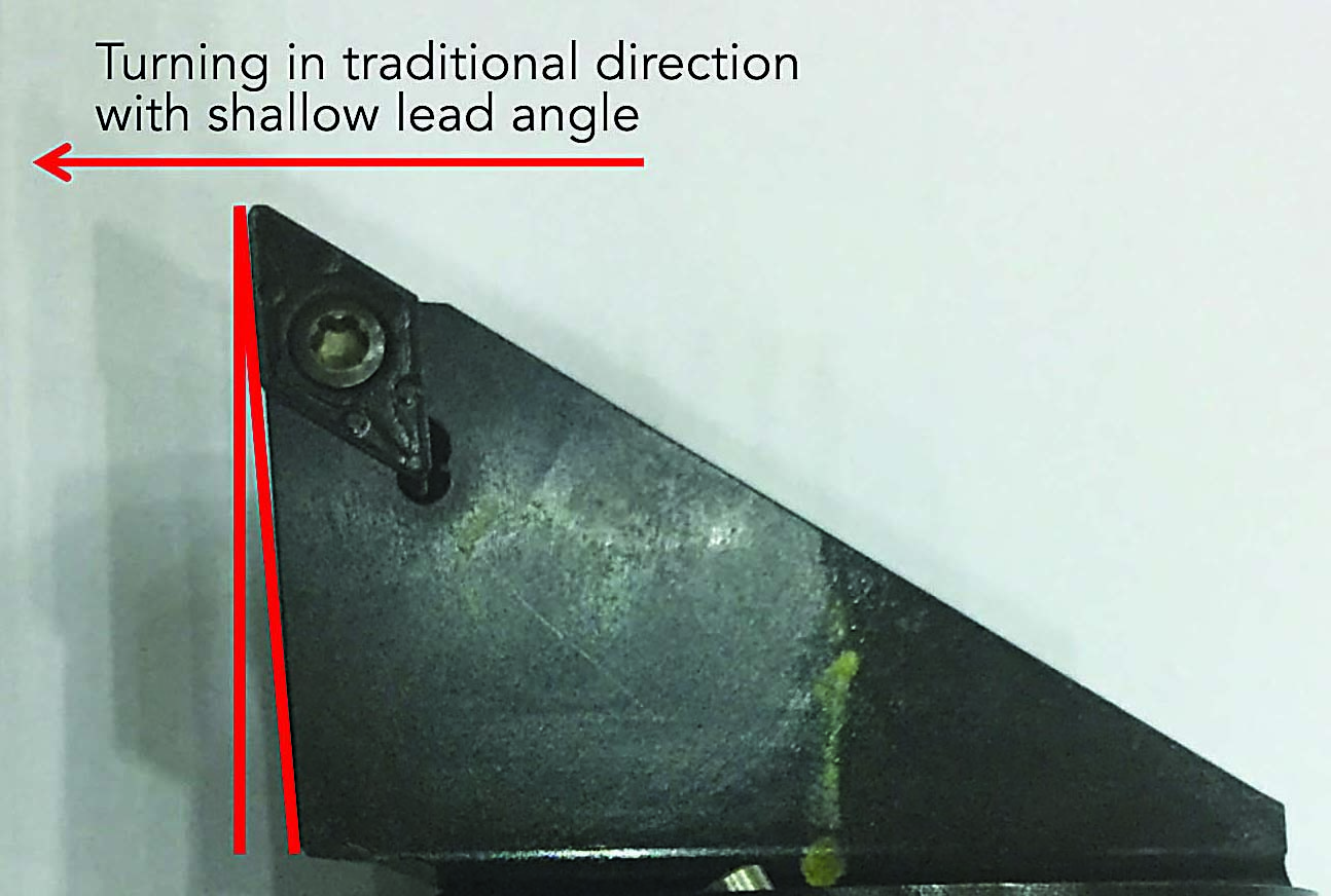
A common tool shape with a shallow lead angle produces a chip thickness roughly equal to the feed rate per revolution. Image courtesy of C. Tate
For a long time, toolmakers have sold turning and facing tools that hold square, triangle or other common-shaped inserts in an orientation that offers large lead angles. These angles allow increased turning feed rates, which exploit chip thinning. However, only recently have the cutting tool manufacturers and CAM software developers started to sell tools and toolpath solutions that can be called innovative.
One of the most effective, simple advances is used for heavy roughing of workpieces—such as large forgings—where high metal-removal rates are required and surface finish requirements and geometric tolerances are loose. Part manufacturers have applied rectangular inserts resembling large bricks of carbide with strong edge geometry. The inserts are held so the long edge is presented to the work in a tool body that creates a steep lead angle. Some manufacturers have demonstrated radial engagement of 1.3″ with feed rates of 0.078 ipr. Compare these measures with the 0.187″ DOC and 0.008 ipr feed rate of the standard CNMG inserts found at most shops.
In the Groove
Plunge turning, groove turning and multidirectional turning are terms that describe the practice of applying rectangular grooving tools to create grooves, along with a multitude of other part geometries. Before the proliferation of affordable CAM software and advanced machine controls, complex groove geometries were made with form tools. Turning tools would be form-ground to match the desired geometry so the programmer needed only to position the tool in the correct axial location and feed it into the part.
With the evolution of affordable software, creative programmers and machinists began using standard grooving tools to create complex geometries and forgo form tools. Cutting tool manufacturers responded with designs that aided this practice. They provided improvements that increased insert stability and research that tuned speed and feed data.
Review the print ads from this magazine to continue
This quick advertiser review unlocks the rest of the article and keeps the full-screen reader focused on the ads instead of the page chrome.


MFGAxis Discussion