Since the dawn of machining, part manufacturers have looked for ways to squeeze greater efficiencies out of existing equipment, materials and labor. CAM and CNC machining were huge steps in the right direction several decades ago. But in recent years, the improvements in machining productivity haven’t been as large.
This is because productivity-enhancing research focused primarily on computerization to streamline toolpath generation and toolpath optimization software, slowing feed rates at corners to reduce stress on tools. Nearly all innovations assumed a parallel-offset toolpath used for roughing parts, not realizing this was the real bottleneck. Ultrahigh- performance toolpath (UHPT) software changes this and improves the way tools cut through material, using high-speed continuous tangent motion rather than sharp, interrupted movements.
Imagine driving through a neighborhood without arterial streets. At each corner, you must slow down or stop at a stop sign, make a turn and proceed for another block while encountering changing traffic conditions. It’s maddeningly inefficient.
That’s how basic toolpaths drive CNC machines. Modeled on manual methodology, existing toolpaths are derived from the geometry being machined. They start with the material boundary and keep stepping in, following the shape of the material until the path collapses on itself. In other words, the tools follow a path regardless of the amount of material they encounter. This is hard on machines and tools.
Now, imagine the same neighborhood is redesigned on a circuitous route, with banked roundabouts and smooth curves instead of corners and stop signs. The amount of traffic is steady; it almost never slows down and never stops. You drive at a high average speed until you reach your destination. Yes, you might travel more distance. But the time and fuel saved and the reduced wear and tear on the car make the circuitous design worthwhile. This is the underlying concept behind UHPT software.
The software works on any shape, open or closed, with any number of features, and integrates with any CAM system. It plans the toolpath based on abilities designed into the machine and cutting tools. By taking advantage of the capabilities of modern machining hardware and avoiding sharp directional changes, it generates toolpaths that assure the machines and cutting tools are used at peak efficiency given existing conditions.
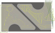
Courtesy of Celeritive Technologies
A standard toolpath (left) makes parallel cuts, requiring numerous stops and starts. UHPT software designs toolpath cuts in continuous motion.
Currently only offered as a 2.5-axis product called VoluMill from Celeritive Technologies Inc., Cave Creek, Ariz., UHPT software is ideal for prismatic parts. The software cuts pockets, steps, slots, channels and other shapes. It can be used with any cutting style and workpiece material, including the hardest metals.
Traditional toolpath technology forces machinists to accommodate worst-case machining conditions to prevent damaging the spindle and prematurely wearing out the cutting tool. Abrupt changes in the amount of material being encountered put excessive force on the part and machine. So programmers and machinists select slower feeds and speeds or make shallower cuts.
UHPT software, on the other hand, allows programmers to select the most appropriate cutting styles and optimal feeds and speeds. This is possible because the software designs toolpaths with no abrupt changes in direction or to the volume of material encountered; the load on the cutting tools and spindle never exceeds user-programmed limits.
Another major advantage is flexibility. UHPT software compares the speed between slotting or side milling an area under given conditions and selects the most efficient approach. In general, UHPT technology minimizes the amount of slot milling because of the excessive amount of material encountered. But when slot milling is the optimal choice, the software reduces the axial DOC and slows the feed, reducing the amount of material encountered and maintaining a consistent load on the tool and spindle. If desired, the programmer can specify only side milling and eliminate slot milling to avoid burying the tool. This is especially useful in hard metals.
For every unique combination of machine, cutting tool and material, a “sweet zone” exists, where an ideal combination of feed rate, spindle speed, DOC and WOC maximizes material removal while obtaining acceptable tool life. Just as cars get better mileage on the freeway compared with stop-and-go city traffic, so do CNC machines and cutting tools function better, last longer and require less maintenance when they run in their sweet zone.
Typical toolpaths frequently encounter “not-so-sweet zones” because the amount of material exposed to the cutting tool fluctuates. NC programmers compensate for the instances where the tool load is excessive by using less aggressive cutting parameters throughout the toolpath. While there are typically hundreds of instances where the cutting tool encounters excess amounts of material in a toolpath, the duration of each is brief, and together they comprise just a small percentage of the overall toolpath length. The unfortunate fallout of this is that the parameters in use are too conservative for the majority of the toolpath.
Conversely, UHPT software designs toolpaths that are free of the instances of excessive tool load, so parameter compromises are not necessary. This enables machine tools and cutting tools to operate under near ideal conditions.
PTD Manufacturing, Detroit Lakes, Minn., is a metal stamping and fabricating facility that recently adopted UHPT software. The software is configured as an add-on module, working within GibbsCAM. PTD uses UHPT software to program 3- and 5-axis vertical mills. After a month in operation, PTD confirmed significant improvements in tool life, scrap and total efficiencies.
Before switching to UHPT technology, PTD roughed pockets using a large inserted tool taking 0.1 " to 0.2 " axial steps. Then, pockets were finished with a solid-carbide endmill. Today, PTD applies a smaller solid-carbide tool, taking full-depth axial cuts, with a 0.02 " to 0.05 " peripheral cut at about five to 10 times the feed rate and rpm.
The most dramatic improvement to date has come from PTD using UHPT technology to mill a large pedestal punch from A-2 tool steel. Previously, it took 22:36 minutes to run the punch with a 3 " inserted shell mill. Now it takes 7:20 minutes with a ½ " carbide ball endmill—a 208 percent increase in efficiency. Throughout the shop, PTD estimates that total machining time has been reduced by about 40 percent.
“UHPT technology creates toolpath cuts much more intelligently, with more aggressive parameters,” said Jake Kopveiler, CNC programmer at PTD. “It has optimized our machine and cutting tool capabilities. The improved cycle time speaks for itself.”
About the Author: Alesa Lightbourne, Ph.D., teaches communications at Chapman University College, and is a freelance writer who covers engineering and high-tech topics. She can be reached at [email protected]. For more information about Celeritive Technologies Inc., call (888) 253-6701, visit www.volumill.com or enter #305 on the IS Form.
Related Glossary Terms
- computer numerical control ( CNC)
computer numerical control ( CNC)
Microprocessor-based controller dedicated to a machine tool that permits the creation or modification of parts. Programmed numerical control activates the machine’s servos and spindle drives and controls the various machining operations. See DNC, direct numerical control; NC, numerical control.
- computer-aided manufacturing ( CAM)
computer-aided manufacturing ( CAM)
Use of computers to control machining and manufacturing processes.
- endmill
endmill
Milling cutter held by its shank that cuts on its periphery and, if so configured, on its free end. Takes a variety of shapes (single- and double-end, roughing, ballnose and cup-end) and sizes (stub, medium, long and extra-long). Also comes with differing numbers of flutes.
- feed
feed
Rate of change of position of the tool as a whole, relative to the workpiece while cutting.
- gang cutting ( milling)
gang cutting ( milling)
Machining with several cutters mounted on a single arbor, generally for simultaneous cutting.
- milling
milling
Machining operation in which metal or other material is removed by applying power to a rotating cutter. In vertical milling, the cutting tool is mounted vertically on the spindle. In horizontal milling, the cutting tool is mounted horizontally, either directly on the spindle or on an arbor. Horizontal milling is further broken down into conventional milling, where the cutter rotates opposite the direction of feed, or “up” into the workpiece; and climb milling, where the cutter rotates in the direction of feed, or “down” into the workpiece. Milling operations include plane or surface milling, endmilling, facemilling, angle milling, form milling and profiling.
- milling machine ( mill)
milling machine ( mill)
Runs endmills and arbor-mounted milling cutters. Features include a head with a spindle that drives the cutters; a column, knee and table that provide motion in the three Cartesian axes; and a base that supports the components and houses the cutting-fluid pump and reservoir. The work is mounted on the table and fed into the rotating cutter or endmill to accomplish the milling steps; vertical milling machines also feed endmills into the work by means of a spindle-mounted quill. Models range from small manual machines to big bed-type and duplex mills. All take one of three basic forms: vertical, horizontal or convertible horizontal/vertical. Vertical machines may be knee-type (the table is mounted on a knee that can be elevated) or bed-type (the table is securely supported and only moves horizontally). In general, horizontal machines are bigger and more powerful, while vertical machines are lighter but more versatile and easier to set up and operate.
- numerical control ( NC)
numerical control ( NC)
Any controlled equipment that allows an operator to program its movement by entering a series of coded numbers and symbols. See CNC, computer numerical control; DNC, direct numerical control.
- parallel
parallel
Strip or block of precision-ground stock used to elevate a workpiece, while keeping it parallel to the worktable, to prevent cutter/table contact.
- slotting
slotting
Machining, normally milling, that creates slots, grooves and similar recesses in workpieces, including T-slots and dovetails.
- toolpath( cutter path)
toolpath( cutter path)
2-D or 3-D path generated by program code or a CAM system and followed by tool when machining a part.
Author
News items authored by Cutting Tool Engineering have been written or edited by the editors of Cutting Tool Engineering magazine. The reports represent material submitted to CTE by outside authors, and edited by CTE editors for style and accuracy.