By CNC Software Inc.
Several decades ago, after years of working as a machinist in his home state, Ohio native Sam Roberts decided to head south in search of manufacturing career opportunities. Weary from his 80-mile commute, he was ready for a change of scenery — and climate.
“I took the chance and drove to Georgia on my last paycheck and a prayer,” he said. “I baked cookies on Highway 5 in Douglasville for a couple of weeks until I found a manufacturing job.”
Through that job and a few others, Roberts honed his manual and CNC machining skills. In 1999, he was introduced to MastercamCAD/CAM software from CNC Software Inc. in Tolland, Connecticut. As a machinist proficient in G code, he was impressed with the software.
“When I saw Mastercam and had an opportunity to see what it could do,” he said, “I thought, ‘Wow, that’s impressive. That’s a lot better than typing in G code all day.’”
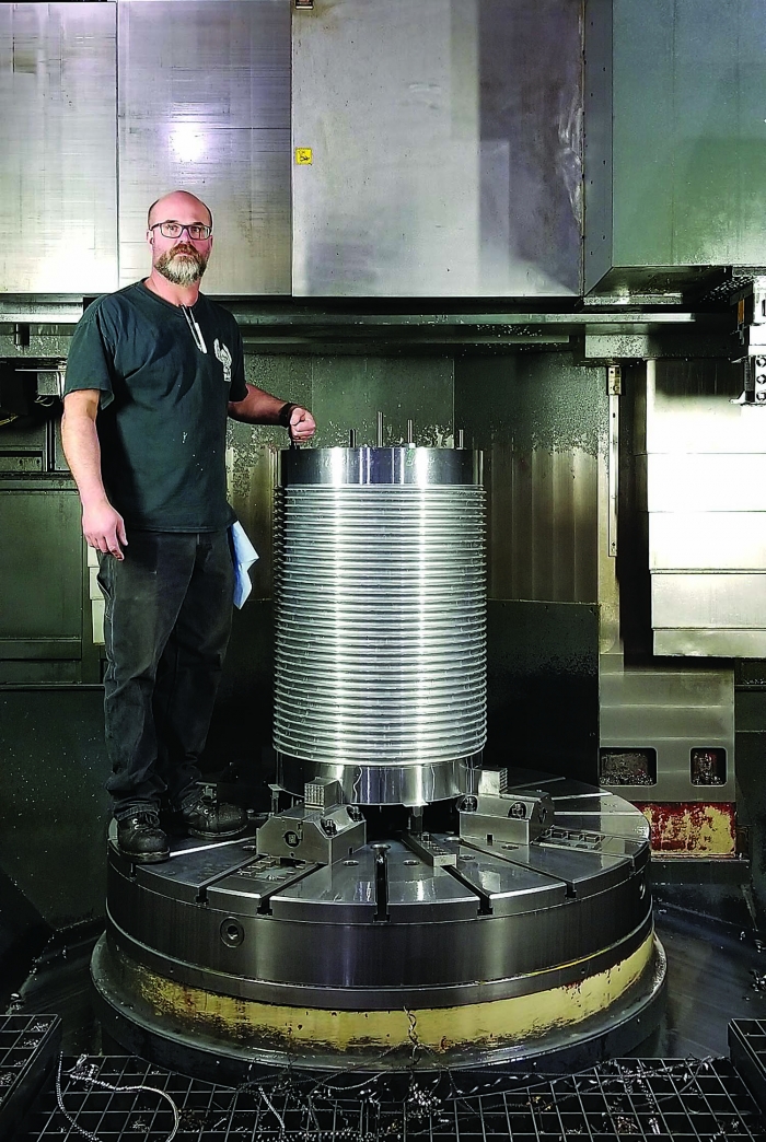
3D-Machine employee Bryan McKinney is pictured with a hoist drum. The part groove was machined on a vertical turning lathe with Mastercam’s Lathe Custom Thread toolpath. Image courtesy of CNC Software
In 2001, Roberts seized a chance to run his own machine shop. Armed with Mastercam version six and a Haas VF-3 vertical machining center, he launched 3D-Machine Inc. Located more than 20 miles northwest of Atlanta in Powder Springs, the full-service shop specializes in precision milling and turning of parts ranging from less than 28 g (1 oz.) to 13,608 kg (30,000 lbs.). Industries served include hydropower and nuclear power, automotive, aerospace, communications and medical.
Over the past 20 years, 3D-Machine has grown at a steady clip. The original 111-sq.-m (1,200-sq.-ft.) facility expanded to 3,530 sq. m (38,000 sq. ft.). A larger space means more employees — currently numbering just under 20 — and bigger machinery, including a horizontal boring mill, lathes and vertical turning lathes.
“I’ve got enough room to grow,” Roberts said. “We do a lot of shaft work, some pump work. We really do anything. If we think we can do it and not have to charge a crazy amount to make the part, we are not afraid to take something on. We’ll do whatever it takes.”
More than 20 years after his first encounter with his favorite CAD/CAM software, he still relies on it for his design and production needs. 3D-Machine stays current in Mastercam by using the latest release, which features Mastercam Mill, Mastercam Lathe, Mastercam Wire and Solids. In addition, the company participated in the beta program for Mastercam 2021. He appreciates the generous selection of toolpaths in the software.
“I recently discovered a new toolpath called Lathe Custom Thread,” Roberts said. “It is phenomenal.”
The toolpath supports custom thread forms and expands support for modeling chucks and chuck jaws. The CAM software supports collet chucks as individual component types, which extends the range of machines that can be supported directly. The toolpath also streamlines and simplifies programming workflow.
By selecting chained geometry in Lathe Custom Thread, a programmer can choose the thread cross section or one of the following parametric definitions: rope, buttress, square or trapezoidal. The toolpath includes Mastercam Mill-Turn simulation enhancements, as well as support for select Swiss machining.
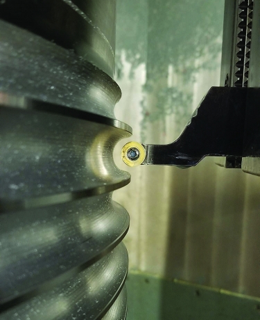
A close-up view is given of a hoist drum groove being machined on a vertical turning lathe programmed with Mastercam’s Lathe Custom Thread toolpath. Image courtesy of CNC Software
3D-Machine recently produced a carbon steel part for a cable reel. The part had a 23.8125 mm (0.9375") pitch and a 10.312 mm (0.406") radius. A 12 mm (0.4724") button tool was used to rough and finish the part. Because the company created the chain, deburring occurred during the process.
The part, a hoist drum, employs a wire rope or cable to lift or lower loads. The grooves keep steel cables from overlapping, which could damage them, and prevent inconsistent lifting and lowering of objects. Due to its size, the drum was machined on a large vertical turning lathe. The selected toolpath is not limited to vertical machining and just as easily can be performed on a horizontal lathe. In this case, the machinist cut a left-handed spiral, so the tool engaged in the cut from the bottom to the top to produce the shape.
“It took us seven hours to put in this groove, which — if you laid (it) out in a straight line — would measure 212 linear feet (64.6 m),” Roberts said. “We had to use a mill and a rotary to make, rough, then finish the part. We did the deburr on a VTL in seven hours. It’s just beautiful.”
Without the Lathe Custom Thread toolpath, part production would have taken at least 40 hours. 3D-Machine reduced production time for the hoist drum by 83%.
“It is very much like threading a part,” Roberts said. “The difference is you are roughing the thread using parameters typically found in straight grooving.”
To ensure that a shape is exactly what the company is looking for, he and his team rely on Verify, a CAM software feature that prevents tool collisions by letting programmers check for gouges, view finished part shapes and visualize inclusion of fixtures on a simulation screen. Productivity increases and problems are addressed before parts are cut. Programmers can confirm on a separate thread while continuing to program, saving production time.
Imagine a groove of any shape. If the chosen tool can profile that shape, the tool can be made to cut that profile at a thread pitch specified by a customer, Roberts said. Big parts traditionally would require large tools in a shape that matched the profile and would necessitate a lot of horsepower. Many parts need a follow rest to keep them from being pulled out of the chuck and center.
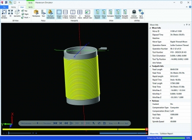
The Verify feature is used to prevent tool collisions and boost productivity during hoist drum machining. Image courtesy of CNC Software
“Mastercam gives us an opportunity to take on work that other machine shops cannot do,” he said. “There are so many jobs that we’ve done because we do 3D surfacing. We have made several parts over the years that we never could have manufactured without CAD/CAM software.”
3D-Machine programmers maintain manufacturer-specific, easy-to-use tool libraries loaded with accurate tool dimensions and data. Directly importing tool data into the CAM program allows more time at the machine. Potential problems can be identified before jobs are brought to the shop floor.
“When I create setup sheets, they include a description of the tool, a toolholder and required pullouts,” Roberts said. “If machinists follow those rules on the shop floor based on the pullouts that we give them, they don’t wreck the holder, they don’t hit clamps, they don’t have any surprises.”
Due to the number of fixtures designed and machined in Mastercam, he and his staff used the software to create a fixture database. They have acquired more than 100 fixtures so far. Anyone producing a part can bring a fixture and his or her part into the CAM software.
“It’s just a great tool,” Roberts said. “By maintaining a database of all our fixtures, we eliminated repetitive processes that we may have had to perform 20 years ago. Now we’re not reinventing the wheel every time we take on a new job.”
Having a reliable CAD/CAM reseller contributes additional value to 3D-Machine’s software investment. Based on his experiences with other software sellers, he rates the support provided by Steve Landkamer, owner of CAD/CAM Solutions Inc. in Snellville, Georgia, and his team as superior.
“Everyone at CAD/CAM Solutions is very helpful, very knowledgeable,” Roberts said. “I usually call Steve when I can’t figure something out. Most of the time, he can walk me through the process and get the issues resolved. They do a phenomenal job over there.”
Thanks to the flexibility of the CAD/CAM software, 3D-Machine can handle parts from less than 0.45 kg (1 lb.) up to 6,804 kg (15,000 lbs.). To date, the largest part machined was a 4,445 kg (9,800 lb.) oil rig valve. He said more than 50% of 3D-Machine’s work would not be possible without the software. In addition, the company boasts significant cost savings by taking advantage of conversion tools in the software.
“I used Mastercam to design and machine a lot of products,” Roberts said. “I’ve designed in it, I’ve drawn up assemblies in it, and I’ve taken parts of the drawing and assembly and converted them from metric stock material to inch. By performing this conversion, we saved $23,000 in material because metric material is so much more expensive in the United States.”
As for expanding business, the company plans to launch an e-commerce website to sell 3D-Machine’s original products, including a coolant nozzle block.
Contact Details
Related Glossary Terms
- boring
boring
Enlarging a hole that already has been drilled or cored. Generally, it is an operation of truing the previously drilled hole with a single-point, lathe-type tool. Boring is essentially internal turning, in that usually a single-point cutting tool forms the internal shape. Some tools are available with two cutting edges to balance cutting forces.
- chuck
chuck
Workholding device that affixes to a mill, lathe or drill-press spindle. It holds a tool or workpiece by one end, allowing it to be rotated. May also be fitted to the machine table to hold a workpiece. Two or more adjustable jaws actually hold the tool or part. May be actuated manually, pneumatically, hydraulically or electrically. See collet.
- collet
collet
Flexible-sided device that secures a tool or workpiece. Similar in function to a chuck, but can accommodate only a narrow size range. Typically provides greater gripping force and precision than a chuck. See chuck.
- computer numerical control ( CNC)
computer numerical control ( CNC)
Microprocessor-based controller dedicated to a machine tool that permits the creation or modification of parts. Programmed numerical control activates the machine’s servos and spindle drives and controls the various machining operations. See DNC, direct numerical control; NC, numerical control.
- computer-aided manufacturing ( CAM)
computer-aided manufacturing ( CAM)
Use of computers to control machining and manufacturing processes.
- coolant
coolant
Fluid that reduces temperature buildup at the tool/workpiece interface during machining. Normally takes the form of a liquid such as soluble or chemical mixtures (semisynthetic, synthetic) but can be pressurized air or other gas. Because of water’s ability to absorb great quantities of heat, it is widely used as a coolant and vehicle for various cutting compounds, with the water-to-compound ratio varying with the machining task. See cutting fluid; semisynthetic cutting fluid; soluble-oil cutting fluid; synthetic cutting fluid.
- fixture
fixture
Device, often made in-house, that holds a specific workpiece. See jig; modular fixturing.
- gang cutting ( milling)
gang cutting ( milling)
Machining with several cutters mounted on a single arbor, generally for simultaneous cutting.
- grooving
grooving
Machining grooves and shallow channels. Example: grooving ball-bearing raceways. Typically performed by tools that are capable of light cuts at high feed rates. Imparts high-quality finish.
- lapping compound( powder)
lapping compound( powder)
Light, abrasive material used for finishing a surface.
- lathe
lathe
Turning machine capable of sawing, milling, grinding, gear-cutting, drilling, reaming, boring, threading, facing, chamfering, grooving, knurling, spinning, parting, necking, taper-cutting, and cam- and eccentric-cutting, as well as step- and straight-turning. Comes in a variety of forms, ranging from manual to semiautomatic to fully automatic, with major types being engine lathes, turning and contouring lathes, turret lathes and numerical-control lathes. The engine lathe consists of a headstock and spindle, tailstock, bed, carriage (complete with apron) and cross slides. Features include gear- (speed) and feed-selector levers, toolpost, compound rest, lead screw and reversing lead screw, threading dial and rapid-traverse lever. Special lathe types include through-the-spindle, camshaft and crankshaft, brake drum and rotor, spinning and gun-barrel machines. Toolroom and bench lathes are used for precision work; the former for tool-and-die work and similar tasks, the latter for small workpieces (instruments, watches), normally without a power feed. Models are typically designated according to their “swing,” or the largest-diameter workpiece that can be rotated; bed length, or the distance between centers; and horsepower generated. See turning machine.
- machining center
machining center
CNC machine tool capable of drilling, reaming, tapping, milling and boring. Normally comes with an automatic toolchanger. See automatic toolchanger.
- milling
milling
Machining operation in which metal or other material is removed by applying power to a rotating cutter. In vertical milling, the cutting tool is mounted vertically on the spindle. In horizontal milling, the cutting tool is mounted horizontally, either directly on the spindle or on an arbor. Horizontal milling is further broken down into conventional milling, where the cutter rotates opposite the direction of feed, or “up” into the workpiece; and climb milling, where the cutter rotates in the direction of feed, or “down” into the workpiece. Milling operations include plane or surface milling, endmilling, facemilling, angle milling, form milling and profiling.
- milling machine ( mill)
milling machine ( mill)
Runs endmills and arbor-mounted milling cutters. Features include a head with a spindle that drives the cutters; a column, knee and table that provide motion in the three Cartesian axes; and a base that supports the components and houses the cutting-fluid pump and reservoir. The work is mounted on the table and fed into the rotating cutter or endmill to accomplish the milling steps; vertical milling machines also feed endmills into the work by means of a spindle-mounted quill. Models range from small manual machines to big bed-type and duplex mills. All take one of three basic forms: vertical, horizontal or convertible horizontal/vertical. Vertical machines may be knee-type (the table is mounted on a knee that can be elevated) or bed-type (the table is securely supported and only moves horizontally). In general, horizontal machines are bigger and more powerful, while vertical machines are lighter but more versatile and easier to set up and operate.
- pitch
pitch
1. On a saw blade, the number of teeth per inch. 2. In threading, the number of threads per inch.
- sawing machine ( saw)
sawing machine ( saw)
Machine designed to use a serrated-tooth blade to cut metal or other material. Comes in a wide variety of styles but takes one of four basic forms: hacksaw (a simple, rugged machine that uses a reciprocating motion to part metal or other material); cold or circular saw (powers a circular blade that cuts structural materials); bandsaw (runs an endless band; the two basic types are cutoff and contour band machines, which cut intricate contours and shapes); and abrasive cutoff saw (similar in appearance to the cold saw, but uses an abrasive disc that rotates at high speeds rather than a blade with serrated teeth).
- threading
threading
Process of both external (e.g., thread milling) and internal (e.g., tapping, thread milling) cutting, turning and rolling of threads into particular material. Standardized specifications are available to determine the desired results of the threading process. Numerous thread-series designations are written for specific applications. Threading often is performed on a lathe. Specifications such as thread height are critical in determining the strength of the threads. The material used is taken into consideration in determining the expected results of any particular application for that threaded piece. In external threading, a calculated depth is required as well as a particular angle to the cut. To perform internal threading, the exact diameter to bore the hole is critical before threading. The threads are distinguished from one another by the amount of tolerance and/or allowance that is specified. See turning.
- toolholder
toolholder
Secures a cutting tool during a machining operation. Basic types include block, cartridge, chuck, collet, fixed, modular, quick-change and rotating.
- toolpath( cutter path)
toolpath( cutter path)
2-D or 3-D path generated by program code or a CAM system and followed by tool when machining a part.
- turning
turning
Workpiece is held in a chuck, mounted on a face plate or secured between centers and rotated while a cutting tool, normally a single-point tool, is fed into it along its periphery or across its end or face. Takes the form of straight turning (cutting along the periphery of the workpiece); taper turning (creating a taper); step turning (turning different-size diameters on the same work); chamfering (beveling an edge or shoulder); facing (cutting on an end); turning threads (usually external but can be internal); roughing (high-volume metal removal); and finishing (final light cuts). Performed on lathes, turning centers, chucking machines, automatic screw machines and similar machines.
About the author
CNC Software Inc. is based in Tolland, Connecticut. For more information about Mastercam CAD/CAM software, call 800-228-2877 or visit www.mastercam.com.