Troubleshooting machining operations can be a daunting task, especially boring operations. This is because when machining the outside of a part, you can see what causes the tool to fail. However, when a tool is buried in a hole, as is the case when boring, you can’t see what is happening to the tool.
If you’ve done any boring—especially small-hole boring with a solid-carbide bar—you’ve probably experienced the following: The boring bar is set at or slightly above centerline and is not larger than the hole. The conditions look good. The program checks out. You feel comfortable about the setup and press the start button. Coolant sprays everywhere, and you notice nothing unusual until the boring bar holder retracts from the part.
At that point, your biggest fear has come true—the tip of the boring bar is missing!

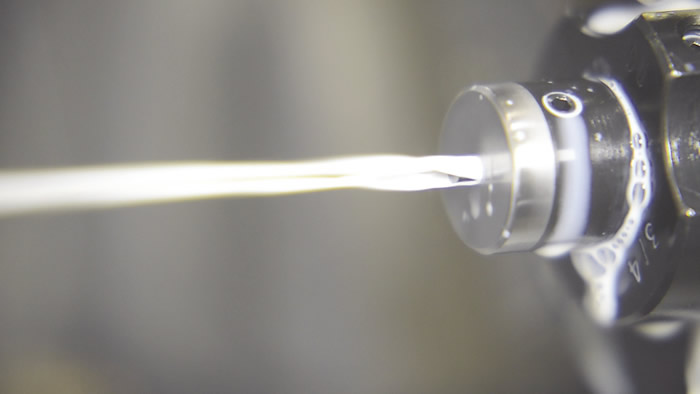
Scientific Cutting Tools is introducing a toolholder with Coolant Ring Technology, which enables coolant to be applied around the circumference of a boring bar. All images courtesy Scientific Cutting Tools.

When this occurs, it is normally because of chip packing or the bar trying to feed past the end of a blind-hole. Upon examination, if the tip of the boring bar is still in the hole and difficult to remove, the hole is most likely packed with chips and you’ve found the cause of the catastrophic failure. In this case, the cutting parameters, such as DOC and feed rate, created a greater volume of chips than could be evacuated. A solution would be to apply a smaller boring bar, if possible. If not, the cutting parameters must be backed off to create a lower volume of chips.
If the broken bar is not in the hole, or is loose in the hole and being obstructed from exiting the hole, you may have tried to feed the bar deeper than the existing hole in the part. A boring bar does not make a good drill!
Rapid Wear
After you’ve made the adjustments necessary to allow the boring bar to finish holes without suffering catastrophic failure, let’s say you decide the production per shift is not acceptable and you feel you’re changing boring bars too frequently. Upon examination of the bar, you determine the tool’s cutting edge has excessive flank wear (Figure 1).
However, the cause of excessive or rapid flank wear can easily be misdiagnosed. Frequently, over time, interrupted cutting or chatter can cause small pits to form on the cutting edge that resemble flank wear.

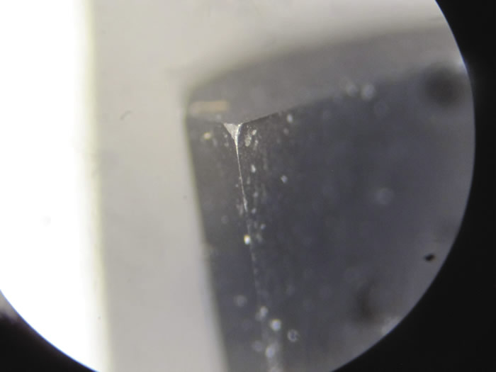
Figure 1. The cause of flank wear is easy to misdiagnose when troubleshooting boring bars.

In addition, what looks like flank wear can start as built-up edge on the top surface of the bar (Figure 2). This is caused by metal from the workpiece welding to the top surface at the cutting edge as a result of heat and pressure during chip formation. Then, at some point, a chip will dislodge the buildup, along with a small piece of carbide from the bar.
To determine if one of these conditions caused the tool to look as though it has experienced flank wear, bore one or two holes and then check to see if any BUE or chipping exists (Figure 3 below).
To reduce BUE, the pressure or heat must be reduced. Pressure results from an overly high DOC and feed rate. Lowering the cutting parameters will reduce the pressure, as well as the heat, but it also lowers productivity. A more productivity-enhancing change would be to apply a coated tool. Coatings reduce the heat that develops as chips move across the cutting surface. A thin, PVD AlTiN coating should be effective, whereas a CVD coating would be too thick and can cause the cutting edge to deteriorate.
Cool Down
Generally, end users try to reduce heat by applying coolant. This is usually simple when machining an OD but can be difficult when boring a small ID, because the hole is partially filled with the boring bar and hot metal chips that need to be cooled.
A coolant line positioned close to the hole often gets in the way, so the best approach is to supply coolant through the boring bar holder. An ample supply of coolant around the circumference of the bar would be ideal, enabling coolant to find the path of least resistance and access the bottom of the bore. Typically, this requires positioning several coolant lines, such as one on the cutting edge side, one directed at the top of the bar and one on the back opposite the cutting edge.

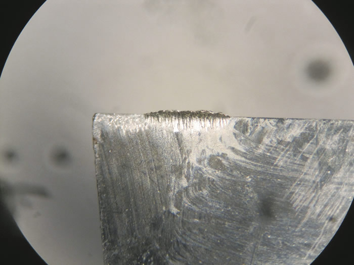
Figure 2. Built-up edge can be misdiagnosed as flank wear after a chip dislodges the buildup
and pulls a piece of carbide with it.

(In response to the need for ample coolant, Scientific Cutting Tools offers a toolholder with Coolant Ring Technology, which enables coolant to be applied around the circumference of a boring bar. This encompasses the bar in a “tube” of coolant.)
If the tool experiences chipping after boring a couple of parts, the most likely cause is an interruption in the part, such as a cross-hole or keyway. When boring an interruption, you may need to apply a tool whose cutting edge has a corner radius, hone or both a corner radius and hone.
If the chipping is not from an interruption, chatter could be the culprit. Chatter is similar to an interruption in that as the tool flexes, it moves downward, then moves back up as it relaxes, shocking the cutting edge. A possible solution is to increase the feed rate. A 10 percent increase can sufficiently boost the pressure to keep the tool in a deflected state, preventing it from relaxing and experiencing a shock.

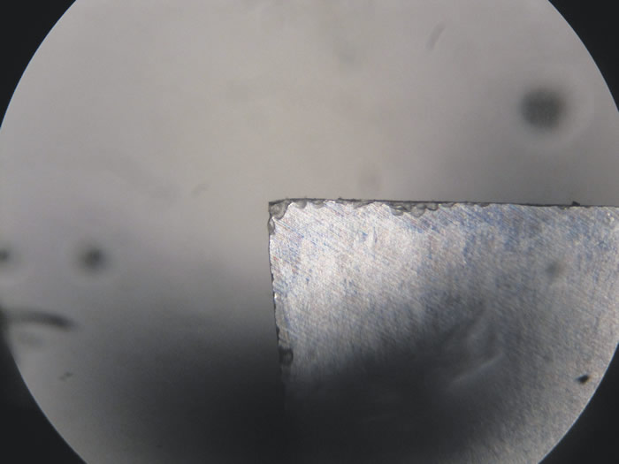
Figure 3. An example of a cutting edge with severe chipping.

There is good news if what you diagnose as flank wear actually is flank wear. Numerous studies on the subject have concluded that a small decrease in cutting speed will make a big difference in the number of minutes a tool can remain in the cut before flank wear becomes an issue. For example, a drop in speed from 400 to 300 sfm might extend cutting tool life from 12 to 40 minutes.
Solving production issues always is a high priority and should be handled in a timely manner. But do not be too quick in identifying failure modes. The wrong diagnosis may trigger changes that are counterproductive—or even make the problem worse.
Contact Details
Related Glossary Terms
- blind-hole
blind-hole
Hole or cavity cut in a solid shape that does not connect with other holes or exit through the workpiece.
- boring
boring
Enlarging a hole that already has been drilled or cored. Generally, it is an operation of truing the previously drilled hole with a single-point, lathe-type tool. Boring is essentially internal turning, in that usually a single-point cutting tool forms the internal shape. Some tools are available with two cutting edges to balance cutting forces.
- boring bar
boring bar
Essentially a cantilever beam that holds one or more cutting tools in position during a boring operation. Can be held stationary and moved axially while the workpiece revolves around it, or revolved and moved axially while the workpiece is held stationary, or a combination of these actions. Installed on milling, drilling and boring machines, as well as lathes and machining centers.
- built-up edge ( BUE)
built-up edge ( BUE)
1. Permanently damaging a metal by heating to cause either incipient melting or intergranular oxidation. 2. In grinding, getting the workpiece hot enough to cause discoloration or to change the microstructure by tempering or hardening.
- built-up edge ( BUE)2
built-up edge ( BUE)
1. Permanently damaging a metal by heating to cause either incipient melting or intergranular oxidation. 2. In grinding, getting the workpiece hot enough to cause discoloration or to change the microstructure by tempering or hardening.
- chatter
chatter
Condition of vibration involving the machine, workpiece and cutting tool. Once this condition arises, it is often self-sustaining until the problem is corrected. Chatter can be identified when lines or grooves appear at regular intervals in the workpiece. These lines or grooves are caused by the teeth of the cutter as they vibrate in and out of the workpiece and their spacing depends on the frequency of vibration.
- chemical vapor deposition ( CVD)
chemical vapor deposition ( CVD)
High-temperature (1,000° C or higher), atmosphere-controlled process in which a chemical reaction is induced for the purpose of depositing a coating 2µm to 12µm thick on a tool’s surface. See coated tools; PVD, physical vapor deposition.
- coolant
coolant
Fluid that reduces temperature buildup at the tool/workpiece interface during machining. Normally takes the form of a liquid such as soluble or chemical mixtures (semisynthetic, synthetic) but can be pressurized air or other gas. Because of water’s ability to absorb great quantities of heat, it is widely used as a coolant and vehicle for various cutting compounds, with the water-to-compound ratio varying with the machining task. See cutting fluid; semisynthetic cutting fluid; soluble-oil cutting fluid; synthetic cutting fluid.
- cutting speed
cutting speed
Tangential velocity on the surface of the tool or workpiece at the cutting interface. The formula for cutting speed (sfm) is tool diameter 5 0.26 5 spindle speed (rpm). The formula for feed per tooth (fpt) is table feed (ipm)/number of flutes/spindle speed (rpm). The formula for spindle speed (rpm) is cutting speed (sfm) 5 3.82/tool diameter. The formula for table feed (ipm) is feed per tooth (ftp) 5 number of tool flutes 5 spindle speed (rpm).
- feed
feed
Rate of change of position of the tool as a whole, relative to the workpiece while cutting.
- flank wear
flank wear
Reduction in clearance on the tool’s flank caused by contact with the workpiece. Ultimately causes tool failure.
- inner diameter ( ID)
inner diameter ( ID)
Dimension that defines the inside diameter of a cavity or hole. See OD, outer diameter.
- outer diameter ( OD)
outer diameter ( OD)
Dimension that defines the exterior diameter of a cylindrical or round part. See ID, inner diameter.
- physical vapor deposition ( PVD)
physical vapor deposition ( PVD)
Tool-coating process performed at low temperature (500° C), compared to chemical vapor deposition (1,000° C). Employs electric field to generate necessary heat for depositing coating on a tool’s surface. See CVD, chemical vapor deposition.
- toolholder
toolholder
Secures a cutting tool during a machining operation. Basic types include block, cartridge, chuck, collet, fixed, modular, quick-change and rotating.


