Rough-and-ready grinding calculations and an opinionated Viking help quickly determine appropriate grinding parameters.
I spend lots of time on grinding machines sorting out problems and improving efficiency. While on the machines I’m asked lots of questions and my answer is always the same.
Question: “Is this dresser speed correct?” Answer: “I dunnknow.” “What coolant flow rate should I have?” “I dunnknow.” “Is this wheel speed good?” “I dunnknow.”
This answer doesn’t win me many admirers, but it’s an honest one. Why? Because just about any dresser speed, flow rate or wheel speed will work—as long as the other parameters are correct.
All images: J. Badger
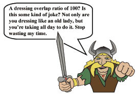
The Grinding Viking gives valuable—if sometimes impolite—advice about your grinding parameters.
Why would just about any dresser speed work? Because a slow dresser speed is fine as long as the wheel rpm is slow, and a fast dresser speed is fine as long as the wheel rpm is fast. In other words, I’m not interested in dressing speeds; I’m interested in the dressing overlap ratio, or how many times a given point on the wheel hits the dressing diamond during the dress. A high overlap ratio dulls a wheel, whereas a small overlap ratio gives a sharp wheel.
Similarly, I’m not interested in coolant flow rates, but rather coolant velocity. The flow rate might be OK—or disastrous, depending on the size of the nozzles. And I’m not that interested in wheel speeds; I’m more interested in aggressiveness values and material-removal rates.
To determine these parameters requires some calculations. They’re usually simple, but breaking out the pen, paper and calculator and scribbling away with oily hands on the cluttered table next to the grinder gets messy.
Calculating flow rate on paper can be a scary proposition.
So, during the past few years I’ve developed The Grinder’s Toolbox, a rough-and-ready spreadsheet for quickly calculating grinding, dressing, sticking and cooling parameters: material-removal rates, aggressiveness values, dresser speed ratios, dresser overlap ratios, OD grinding overlap ratios, continuous-dress dressing DOCs, coolant velocities and pressures, and pump and nozzle sizes. Then I get on the machine, enter the parameters and know immediately if they’re in the ballpark.
For example, a few months ago I got a call from a company having major burn problems on one of their machines. The owner was in a panic because parts were coming out “toasty.” We methodically covered the checklist of grinding, cooling and dressing parameters. One-by-one, I plugged them into the spreadsheet to see if they were reasonable. They were, except for the dressing parameters.
The company was using a rotary plunge roll to form dress. The roll was 3 " in diameter and running at 300 rpm. The 350mm wheel was running at 70 m/sec. unidirectionally, plunging into the roll at 0.02 ipm and then dwelling 3 seconds.
The operator looked at me and asked whether the parameters were good. Of course, my answer was “I dunnknow. That’s a lot of numbers and a lot of different units.”
Then I pulled out The Grinder’s Toolbox and punched in the parameters. Sixty seconds later I had the three meaningful values: speed ratio, plunge depth and the number of dwell revolutions.
Table 1: Dressing
|
Output |
Inputs |
What it tells |
|
| Plunge roll6 |
Speed ratio Vdresser/Vwheel |
1. Dresser velocity1 2. Wheel velocity1 3. Unidirectional or antidirectional |
The aggressiveness of the dress, risk of chatter and burn |
|
Dressing depth in µm/wheel revolution |
1. Plunge speed 2. Wheel rpm2 |
The aggressiveness of the dress,risk of chatter and burn |
|
|
Dwell revolutions |
1. Dwell time 2. Wheel rpm2 |
Whether wheel will be true, wheel dulling due to excessive revolutions |
|
| Traverse disc6 |
Speed ratio Vdresser/Vwheel |
1. Dresser velocity1 2. Wheel velocity1 3. Unidirectional or antidirectional |
The aggressiveness of the dress, risk of chatter and burn |
|
Overlap ratio or dressing lead |
1. Traverse speed3 2. Wheel rpm2 3. Diamond diameter |
The aggressiveness of the dress, risk of chatter and burn |
|
| Single point |
Overlap ratio or dressing lead |
1. Traverse speed3 2. Wheel rpm2 3. Diamond diameter4 |
The sharpness of the wheel, risk of chatter and burn, whether grits are being missed due to high velocity |
| Superabrasives sticking |
Sticking aggressiveness |
1. Stick plunge speed5 2. Wheel velocity1 |
Whether you’re sticking sufficiently hard |
|
Grit ratio |
1. Wheel grit size 2. Stick grit size |
Whether you have the right stick grit size to penetrate between the superabrasive grits |
1. Or diameter and rpm, 2. Or velocity and diameter, 3. Or wheel width and time to traverse, 4. Or width of diamond-covered area, 5. Or stick length and time to stick, and 6. For Al2O3 and CBN wheels.
The speed ratio was +0.17. That will make a wheel quite dull. The plunge depth was 0.13μm per wheel revolution, also dulling the wheel. And the wheel was dwelling 191 revolutions—far too many, further dulling the wheel.
It was obvious the company was dulling its wheel in three different ways, causing atrocious burn. We set about fixing this.
However, we had to deal with machine restraints. The roll speed was fixed, so we played with wheel speeds and plunge speeds until we found a combination that provided a sharp wheel and a slow enough feed rate not to cause chatter.
Why did we need my spreadsheet? If we changed the wheel speed to give us a ratio we liked, we would have inadvertently changed the plunge depth and number of dwell revolutions. Entering all the possibilities into a calculator would have taken all day.
But with The Grinder’s Toolbox we quickly punched in numbers and saw the results. We ended up dropping the wheel speed during dressing to 20 m/sec., providing a speed ratio of +0.6, which gives a sharp wheel. We then increased the plunge speed to 0.04 ipm, which gives a dressing depth of 0.93μm per wheel revolution. That also provides a sharp wheel. Finally, we dropped dwell time to 2.0 seconds, giving us 36 wheel revolutions. The result was a sharp wheel that immediately eliminated the burn issue.
The Real Question
If these calculations are so easy, why aren’t CNC programmers entering these parameters into their grinding machines? I do not know! While many of these concepts are well known, OEMs are building expensive grinding machines but are not covering the basics such as telling the operator his dressing parameters are dulling the wheel, his coolant pressure is too low or that he risks generating chatter.
The most popular sheet in The Grinder’s Toolbox is the cooling section. There, you can input the coolant pressure, and the spreadsheet indicates immediately coolant exit velocity and whether you’re matching the wheel speed. Or you can enter pump size and desired coolant velocity, and the spreadsheet will tell you exactly what size the nozzle opening should be. I use it all the time to size nozzles and booster pumps and determine flow rates.
Table 2: Cooling
| Output | Inputs | What it tells |
|
Coolant velocity |
1. Coolant pressure at nozzle |
To see if you are matching your wheel speed |
|
Coolant pressure |
1. Wheel velocity |
To determine the pressure you need at the outlet |
|
Flow rate |
1. Coolant exit velocity 2. Nozzle size(s) |
To see if your pump can deliver that amount or if your drainage can handle that amount |
|
Nozzle size(s) |
1. Pump flow rate 2. Wheel velocity |
To determine what size nozzles you need for your pump, if your current nozzle opening are too large |
|
Pump power |
1. Flow rate 2. Coolant velocity |
For sizing pumps and booster pumps |
Table 3: Grinding
|
Output |
Inputs |
What it tells |
|
|
Aggressiveness |
1. DOC 2. Wheel diameter 3. Feed rate (velocity) 4. Wheel speed |
If we are in the “sweet spot” for a self-sharpening wheel, if we are at risk for wheel dulling |
|
|
Material-removal rate |
1. DOC 2. Feed rate (velocity) |
How quickly we’re removing material, risk of burn |
|
|
Speed ratio Vwheel/Vworkpiece |
1. Wheel velocity1 2. Workpiece velocity |
Risk of chatter, risk of burn |
|
|
Aggressiveness |
1. Plunge velocity 2. Wheel diameter 3. Workpiece diameter 4. Workpiece rpm2 5. Wheel speed1 6. ID or OD grinding |
If we are in the “sweet spot” for a self-sharpening wheel, if we are at risk for wheel dulling |
|
|
Material-removal rate |
1. Plunge velocity 2. Workpiece diameter |
How quickly we’re removing material, risk of burn |
|
|
Speed ratio Vwheel/Vworkpiece |
1. Wheel velocity1 2. Workpiece velocity1 |
Risk of chatter, risk of burn |
|
|
Aggressiveness at leading edge |
1. DOC 2. Wheel diameter 3. Workpiece diameter 4. Workpiece rpm2 5. Wheel speed1 6. ID or OD Grinding |
If we are in the “sweet spot” for a self-sharpening wheel, if we are at risk for wheel dulling |
|
|
Material-removal rate |
1. DOC 2. Traverse velocity |
How quickly we’re removing material, risk of burn |
|
|
Overlap ratio |
1. Traverse velocity 2. Workpiece rpm |
How much of the wheel is grinding and how much of the wheel is “cleaning up,” risk of dulling, risk of chatter |
|
|
Speed ratio Vwheel/Vworkpiece |
1. Wheel velocity1 2. Workpiece velocity1 |
Risk of chatter, risk of burn |
Table 4: Conversions and other calculations
| Measurement | Inputs |
|
Hardness |
Vickers ↔ Rockwell |
|
Wheel velocity |
Surface feet per minute (sfm) ↔ m/sec. |
|
Wheel or roll velocity |
1. Wheel or roll diameter 2. Wheel or roll rpm |
|
Wheel or roll rpm |
1. Wheel or roll velocity 2. Wheel or roll diameter |
|
Machine stiffness |
1. Wheelhead displacement 2. Force on wheel |
|
Push-off |
Machine power and machine stiffness |
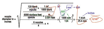
For example, let’s say you’ve just bought a fancy, high-pressure, constant-flow, piston-driven coolant pump. The plate on the back of the pump indicates that the maximum coolant flow rate is 120 liters/min. The wheel is running at 6,000 sfm. You decide to make six equal-sized round nozzles and you want to know what diameter to make them so that you’re using all 120 liters/min. with a coolant velocity that matches wheel velocity. What should you do?
You can guess the diameter should be, say, 0.2 ", fire up the pump and see how things work. Maybe you’ll get it right the first time, but maybe not, in which case you’ll have to make the nozzles a different size.
An alternative is to do the calculation on paper for flow rate based on exit velocity and total orifice area, using the area of a circle, etc. (See equation on page 54.) That’s one scary-looking equation, and not something you’d probably be able to pull off at the machine with your production supervisor breathing down your neck, machines groaning, oil flying around and your cheap, solar-powered calculator cutting out on you.
A third option is to pull out your laptop and fire up The Grinder’s Toolbox. The inputs would be coolant velocity, flow rate and the number of nozzles. That’s it. Thirty seconds later you’d have your answer: a 0.147 "-dia. nozzle.
The Grinding Viking
Remembering recommended ranges and ratios can be tough. In diamond-roll plunge dressing, a depth of 0.1μm per wheel revolution gives a dull wheel, but a depth of 1.0μm per revolution gives a sharp one. In single-point dressing, a dressing lead of 0.2 mm/wheel revolution gives a sharp wheel, but if you’re using a diamond cluster it’ll dull the wheel. In OD traverse grinding, an overlap ratio of 3 is effective for roughing, and a value of 8 is good for finishing.
Remembering all these values is tough. So I also developed The Grinding Viking. He tells if you are within the recommend ranges or making a mistake.
However, The Grinding Viking is not for the thin-skinned. He’s opinionated and sometimes a little rude. But he’s seldom wrong.
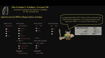
Calculations in The Grinder’s Toolbox for plunge surface grinding. The primary outputs are aggressiveness and material-removal rate.
To Buy or Build
I developed my first Grinder’s Toolbox many years ago. Over time I enhanced it, polishing it off and adding different grinding operations. It is for sale on my Web site.
However, if you know the basic calculations and are Excel-savvy, you can build your own spreadsheet for doing calculations. I’ve met a number of grinding engineers and wheel salespeople who have done just that. Also, several grinding wheel manufacturers have developed their own programs. But it does take time, and debugging can be maddening.
Either way, using predetermined parameters for troubleshooting can take a lot of the guesswork out of improving your grinding operations. CTE
About the Author: Dr. Jeffrey Badger is an independent grinding consultant. His Web site is www.TheGrindingDoc.com.
Related Glossary Terms
- chatter
chatter
Condition of vibration involving the machine, workpiece and cutting tool. Once this condition arises, it is often self-sustaining until the problem is corrected. Chatter can be identified when lines or grooves appear at regular intervals in the workpiece. These lines or grooves are caused by the teeth of the cutter as they vibrate in and out of the workpiece and their spacing depends on the frequency of vibration.
- computer numerical control ( CNC)
computer numerical control ( CNC)
Microprocessor-based controller dedicated to a machine tool that permits the creation or modification of parts. Programmed numerical control activates the machine’s servos and spindle drives and controls the various machining operations. See DNC, direct numerical control; NC, numerical control.
- coolant
coolant
Fluid that reduces temperature buildup at the tool/workpiece interface during machining. Normally takes the form of a liquid such as soluble or chemical mixtures (semisynthetic, synthetic) but can be pressurized air or other gas. Because of water’s ability to absorb great quantities of heat, it is widely used as a coolant and vehicle for various cutting compounds, with the water-to-compound ratio varying with the machining task. See cutting fluid; semisynthetic cutting fluid; soluble-oil cutting fluid; synthetic cutting fluid.
- cubic boron nitride ( CBN)
cubic boron nitride ( CBN)
Crystal manufactured from boron nitride under high pressure and temperature. Used to cut hard-to-machine ferrous and nickel-base materials up to 70 HRC. Second hardest material after diamond. See superabrasive tools.
- dressing
dressing
Removal of undesirable materials from “loaded” grinding wheels using a single- or multi-point diamond or other tool. The process also exposes unused, sharp abrasive points. See loading; truing.
- feed
feed
Rate of change of position of the tool as a whole, relative to the workpiece while cutting.
- grinding
grinding
Machining operation in which material is removed from the workpiece by a powered abrasive wheel, stone, belt, paste, sheet, compound, slurry, etc. Takes various forms: surface grinding (creates flat and/or squared surfaces); cylindrical grinding (for external cylindrical and tapered shapes, fillets, undercuts, etc.); centerless grinding; chamfering; thread and form grinding; tool and cutter grinding; offhand grinding; lapping and polishing (grinding with extremely fine grits to create ultrasmooth surfaces); honing; and disc grinding.
- grinding wheel
grinding wheel
Wheel formed from abrasive material mixed in a suitable matrix. Takes a variety of shapes but falls into two basic categories: one that cuts on its periphery, as in reciprocating grinding, and one that cuts on its side or face, as in tool and cutter grinding.
- grit size
grit size
Specified size of the abrasive particles in grinding wheels and other abrasive tools. Determines metal-removal capability and quality of finish.
- hardness
hardness
Hardness is a measure of the resistance of a material to surface indentation or abrasion. There is no absolute scale for hardness. In order to express hardness quantitatively, each type of test has its own scale, which defines hardness. Indentation hardness obtained through static methods is measured by Brinell, Rockwell, Vickers and Knoop tests. Hardness without indentation is measured by a dynamic method, known as the Scleroscope test.
- inches per minute ( ipm)
inches per minute ( ipm)
Value that refers to how far the workpiece or cutter advances linearly in 1 minute, defined as: ipm = ipt 5 number of effective teeth 5 rpm. Also known as the table feed or machine feed.
- inner diameter ( ID)
inner diameter ( ID)
Dimension that defines the inside diameter of a cavity or hole. See OD, outer diameter.
- outer diameter ( OD)
outer diameter ( OD)
Dimension that defines the exterior diameter of a cylindrical or round part. See ID, inner diameter.
- polishing
polishing
Abrasive process that improves surface finish and blends contours. Abrasive particles attached to a flexible backing abrade the workpiece.
- sawing machine ( saw)
sawing machine ( saw)
Machine designed to use a serrated-tooth blade to cut metal or other material. Comes in a wide variety of styles but takes one of four basic forms: hacksaw (a simple, rugged machine that uses a reciprocating motion to part metal or other material); cold or circular saw (powers a circular blade that cuts structural materials); bandsaw (runs an endless band; the two basic types are cutoff and contour band machines, which cut intricate contours and shapes); and abrasive cutoff saw (similar in appearance to the cold saw, but uses an abrasive disc that rotates at high speeds rather than a blade with serrated teeth).
- stiffness
stiffness
1. Ability of a material or part to resist elastic deflection. 2. The rate of stress with respect to strain; the greater the stress required to produce a given strain, the stiffer the material is said to be. See dynamic stiffness; static stiffness.
- surface grinding
surface grinding
Machining of a flat, angled or contoured surface by passing a workpiece beneath a grinding wheel in a plane parallel to the grinding wheel spindle. See grinding.
- web
web
On a rotating tool, the portion of the tool body that joins the lands. Web is thicker at the shank end, relative to the point end, providing maximum torsional strength.
Author

Jeffrey A. Badger, Ph.D., is an independent grinding expert. He will be giving his 3-day High Intensity Grinding Course from Sept. 26-28 in Columbia, S.C., hosted by S.L. Munson. Visit www.thegrindingdoc.com for details. He can be reached by phone at 512-934-1857 or via email at [email protected].