It has taken some time, but cermet inserts are finally finding their place as turning tools in American machine shops. U.S. users are learning that for high-speed finishing cuts cermets perform better than even coated carbide inserts, and their use reduces machining costs. In one application, for instance, a manufacturer switched from coated carbide to TNMG332 cermet inserts to turn 1043 steel and found that the number of pieces machined per cutting edge increased nearly 400% (Figure 1). Machinists also are finding a constantly expanding number of applications that are right for cermets. Advances in the formulation of cermets have broadened the tool material’s range, and the trend toward near-net-shape manufacturing, which requires only light stock removal, has increased the number of applications that can benefit from cermet’s unique performance characteristics.
Cermets are hybrid materials. Their name suggests a hardness like ceramic (the "cer-" part of the name) with a toughness like metal (the "-met" part). Manufacturers typically use titanium carbide (TiC), titanium nitride (TiN), and titanium carbonitride (TiCN) for the hard pArticles. Because these hard pArticles are very chemically and thermally stable, they impart a high degree of wear resistance to the cermet material. The cermet’s composition may also contain tungsten, tantalum, nickel, cobalt, aluminum, molybdenum, and vanadium as well as other materials. The binder usually includes nickel, cobalt, and molybdenum. The toughness of the metallic binder gives the cermet a shock resistance that exceeds the shock resistance of an exclusively ceramic material. Because the cermet can resist shocks better than ceramic can, cermet tools have a wider application range than ceramic tools have and are less likely to be damaged when turning with interrupted cuts.
Figure 2 compares the hardness and toughness of TiCN-base cermet to other cutting tool materials. As can be seen from its position near the center of the group of materials, cermet offers a balance between hardness and toughness. Its properties place it in the same group with carbides and coated carbides, but it is harder than the carbide grades.
Users must understand that cermets are not general-purpose cutting tools, however. They are most successfully used for finishing and light roughing applications. Cermets can be used to machine most types of steel and stainless steel. Cermets should not be used for rough copy turning. And, depending on the machining application and workpiece material, feed rates in excess of 0.012 ipr should be avoided, because thicker chips may damage the cutting edges. When feed rates approach the 0.010-0.012 ipr limit, the cutting speed should be reduced.
Cermet Evolution
Cermet’s inherent brittleness has always been a challenge to developers who hope that a mating of hard pArticles and metal binders will yield a material with the desirable properties of both. Over the years, cermet manufacturers have mixed a number of components trying to produce a material that would be strong and resistant to oxidation at high temperatures and tough enough to resist shocks. Cutting tool manufacturers have been especially interested in finding a material that is both hard enough and tough enough to take the stresses and elevated temperatures that accompany increases in speed and feed rates.
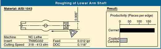
Figure 1:One user was able to turn nearly four times as many steel shafts per cutting edge when he switched from coated carbide to cermet inserts.
In 1956, cutting tool manufacturers pinned their hopes on a new TiC/nickel-alloy cermet that contained molybdenum and carbon. The cutting tool material was able to perform well at high speeds and high temperatures, but it failed to win over users, because cermet was unable to endure interrupted cutting applications. Machinists inevitably compared the cermet tools to the tougher tungsten-carbide tools that were available then. They saw tungsten carbide perform satisfactorily even when their jobs involved heavy metal-removal rates, exotic materials, or older and less rigid machines. Because these same conditions chipped or shattered cermet tools, the machinists concluded that tungsten carbide was the better tool material. As a result, the popularity of cermet cutting tools faded.
Japanese users had a different opinion, however. For them, the limited range of cermets was not a severe liability. In 1960, when Mitsubishi, Sumitomo, and Toshiba began to sell cermet inserts in Japan, the tools quickly found their niche. Near-net machining and newer, more rigid machines were more common in Japan, and the use of exotic workpiece materials was much rarer. The Japanese acceptance of cermet cutting tools spurred manufacturers in that country to develop improved inserts with tungsten carbide and tantalum carbide added to make them tougher. They weren’t able to produce a cermet that was as tough as tungsten carbide, however, and so the use of cermet inserts remained limited to light finishing applications.
Another advance in cermet properties came in 1973, when Japanese producers began adding TiN to the hard-particle portion of the insert to create a cermet with a finer microstructure. This modification resulted in an insert with improved high-temperature strength and oxidation resistance.
A High-Speed Turning Tool
All of these improvements have led to a cermet cutting tool that is ideal for users who want to crank up the speed on their lathes when turning steel. In a high-speed operation, the friction between the insert and the workpiece can raise the temperature at the cutting edge to 1000° C. Such heat can quickly degrade a tungsten-carbide tool’s mechanical properties. But high temperatures have less of an effect on a cermet’s hardness, transverse rupture strength, and oxidation resistance. In steel, the performance of cermet tools will even surpass that of coated tungsten-carbide tools.
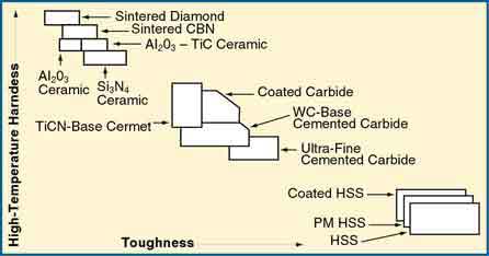
Figure 2:As this chart indicates, TiCN-base cermets are harder than tungsten-carbide and HSS cutting tools and tougher than diamond and ceramic tools.
Cermet owes its high hot hardness to the primary component of its hard pArticles, TiC. At elevated temperatures, the TiC compound’s hardness is comparable to any carbide, nitride, or oxide used in cutting tools. This hardness enhances a cermet insert’s flank-wear resistance. A cermet tool’s high transverse rupture strength contributes to its resistance to chipping or fracturing, but these problems are still the major causes of cermet insert failure.
With their lower value of free energy formation, cermet tools are better able to avoid crater wear, which is caused by thermochemical reactions between chips and the insert. These reactions occur at a much slower pace with cermet inserts. This is because the hard pArticles in the material resist diffusion on the tool’s rake face. The stability of the material minimizes oxidation and crater wear by making the tool chemically stable at high temperatures. Cermets also resist built-up edge, because adhesion corresponds to the amount of solubility of the hard material into iron. It is believed that low solubility makes it difficult for the workpiece material to adhere to the cutting edge of the tool.
Tungsten-carbide tools do have an advantage over cermets in one area. They possess greater shock resistance. Shock resistance is a function of the bonding strength between a material’s hard pArticles and its binder, and tungsten-carbide bonds are stronger. However, cermet manufacturers have greatly improved the binders in their products, and this has led to cutting tools that are shock-resistant enough to be used for milling as well as turning in interrupted cuts.
Speed is not the only reason users turn to cermets, however. The inserts can also be used to produce mirror-like finishes. The tool’s oxidation resistance reduces notching at the cutting edge in finishing applications, and this minimizes damage to the workpiece surface. The smoothness of the surface finish also is enhanced by the inserts’ ability to turn at high speeds and maintain a keen cutting edge.
Cutting-Edge Cermets
Until recently, the idea of coated cermet cutting tools was not considered. It was assumed that a coating would not improve the cermet’s performance significantly, because the cutting tool material already contained the components most coating manufacturers use to create a hard protective shell around tungsten-carbide tools. But recent studies of coated cermets have shown them to be less subject to wear than uncoated cermets in certain machining operations (Figure 3).
Studies have also been used to find the optimum coating and coating method for cermet tools. In one series of turning and interrupted-turning tests, the mechanical properties and cutting performance of TiN-coated cermets coated using a physical-vapor-deposition (PVD) process and a chemical-vapor-deposition (CVD) process were compared. The coated cermets were also compared to uncoated cermets.
After coating, the microstructure, thickness, grain size, microhardness, residual stress, and adhesive strength of the TiN coating were examined. It was found that PVD TiN coatings were of a considerably finer texture than those formed by the CVD method. Also, the hardness of the film deposited by the CVD method was low compared to the PVD film’s hardness. This was attributed to the diffusion of the binder metal from the cermet into the film, as well as the coarser grain size. The adhesive strength of the film deposited by CVD was low as well.
The transverse rupture strength of both the CVD- and PVD-coated tools was less than the transverse rupture strength of the uncoated tools, but this was to be expected. A similar reduction of transverse rupture strength is seen in coated tungsten-carbide tools. Despite this reduction in an important property, the coating of the cermet tools did yield enough improvement in performance to justify the use of coated cermets in many situations.
At least one coated cermet is already on the market. It is designed to turn various steels at low to moderate cutting speeds with or without coolant. This coated cermet insert is especially suited to the turning of carbon steel. The grade’s tough substrate ensures edge toughness and thermal shock resistance, while its PVD-coated titanium-compound layer provides for longer tool life and resistance to built-up edge.
Although R&D has produced cermet cutting tools that are far superior to those first introduced in the 1950s, they do not represent all that can be achieved. Cermet manufacturers, especially in Japan, are still quite actively pursuing further improvements. Their work ensures that future cermet cutting tools will have an even broader range of machining characteristics.
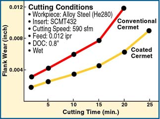
Figure 3: In one test comparison of coated and uncoated cermet cutting tools, coated cermets showed significantly less flank wear.
About the Authors
Ronald Biagiotti is executive vice president, Advanced Alloys and Machinery Division, Marketing and Technical Services, and Robert Macek is manager of Technical Services for Mitsubishi Materials USA Corp., Garden Grove, CA.
Related Glossary Terms
- alloys
alloys
Substances having metallic properties and being composed of two or more chemical elements of which at least one is a metal.
- built-up edge ( BUE)
built-up edge ( BUE)
1. Permanently damaging a metal by heating to cause either incipient melting or intergranular oxidation. 2. In grinding, getting the workpiece hot enough to cause discoloration or to change the microstructure by tempering or hardening.
- cermets
cermets
Cutting tool materials based mostly on titanium carbonitride with nickel and/or cobalt binder. Cermets are characterized by high wear resistance due to their chemical and thermal stability. Cermets are able to hold a sharp edge at high cutting speeds and temperatures, which results in exceptional surface finish when machining most types of steels.
- chemical vapor deposition ( CVD)
chemical vapor deposition ( CVD)
High-temperature (1,000° C or higher), atmosphere-controlled process in which a chemical reaction is induced for the purpose of depositing a coating 2µm to 12µm thick on a tool’s surface. See coated tools; PVD, physical vapor deposition.
- coolant
coolant
Fluid that reduces temperature buildup at the tool/workpiece interface during machining. Normally takes the form of a liquid such as soluble or chemical mixtures (semisynthetic, synthetic) but can be pressurized air or other gas. Because of water’s ability to absorb great quantities of heat, it is widely used as a coolant and vehicle for various cutting compounds, with the water-to-compound ratio varying with the machining task. See cutting fluid; semisynthetic cutting fluid; soluble-oil cutting fluid; synthetic cutting fluid.
- cutting speed
cutting speed
Tangential velocity on the surface of the tool or workpiece at the cutting interface. The formula for cutting speed (sfm) is tool diameter 5 0.26 5 spindle speed (rpm). The formula for feed per tooth (fpt) is table feed (ipm)/number of flutes/spindle speed (rpm). The formula for spindle speed (rpm) is cutting speed (sfm) 5 3.82/tool diameter. The formula for table feed (ipm) is feed per tooth (ftp) 5 number of tool flutes 5 spindle speed (rpm).
- cutting tool materials
cutting tool materials
Cutting tool materials include cemented carbides, ceramics, cermets, polycrystalline diamond, polycrystalline cubic boron nitride, some grades of tool steels and high-speed steels. See HSS, high-speed steels; PCBN, polycrystalline cubic boron nitride; PCD, polycrystalline diamond.
- diffusion
diffusion
1. Spreading of a constituent in a gas, liquid or solid, tending to make the composition of all parts uniform. 2. Spontaneous movement of atoms or molecules to new sites within a material.
- feed
feed
Rate of change of position of the tool as a whole, relative to the workpiece while cutting.
- flank wear
flank wear
Reduction in clearance on the tool’s flank caused by contact with the workpiece. Ultimately causes tool failure.
- gang cutting ( milling)
gang cutting ( milling)
Machining with several cutters mounted on a single arbor, generally for simultaneous cutting.
- hardness
hardness
Hardness is a measure of the resistance of a material to surface indentation or abrasion. There is no absolute scale for hardness. In order to express hardness quantitatively, each type of test has its own scale, which defines hardness. Indentation hardness obtained through static methods is measured by Brinell, Rockwell, Vickers and Knoop tests. Hardness without indentation is measured by a dynamic method, known as the Scleroscope test.
- high-speed steels ( HSS)
high-speed steels ( HSS)
Available in two major types: tungsten high-speed steels (designated by letter T having tungsten as the principal alloying element) and molybdenum high-speed steels (designated by letter M having molybdenum as the principal alloying element). The type T high-speed steels containing cobalt have higher wear resistance and greater red (hot) hardness, withstanding cutting temperature up to 1,100º F (590º C). The type T steels are used to fabricate metalcutting tools (milling cutters, drills, reamers and taps), woodworking tools, various types of punches and dies, ball and roller bearings. The type M steels are used for cutting tools and various types of dies.
- mechanical properties
mechanical properties
Properties of a material that reveal its elastic and inelastic behavior when force is applied, thereby indicating its suitability for mechanical applications; for example, modulus of elasticity, tensile strength, elongation, hardness and fatigue limit.
- microhardness
microhardness
Hardness of a material as determined by forcing an indenter such as a Vickers or Knoop indenter into the surface of the material under very light load; usually, the indentations are so small that they must be measured with a microscope. Capable of determining hardness of different microconstituents within a structure or measuring steep hardness gradients such as those encountered in casehardening.
- microstructure
microstructure
Structure of a metal as revealed by microscopic examination of the etched surface of a polished specimen.
- milling
milling
Machining operation in which metal or other material is removed by applying power to a rotating cutter. In vertical milling, the cutting tool is mounted vertically on the spindle. In horizontal milling, the cutting tool is mounted horizontally, either directly on the spindle or on an arbor. Horizontal milling is further broken down into conventional milling, where the cutter rotates opposite the direction of feed, or “up” into the workpiece; and climb milling, where the cutter rotates in the direction of feed, or “down” into the workpiece. Milling operations include plane or surface milling, endmilling, facemilling, angle milling, form milling and profiling.
- physical vapor deposition ( PVD)
physical vapor deposition ( PVD)
Tool-coating process performed at low temperature (500° C), compared to chemical vapor deposition (1,000° C). Employs electric field to generate necessary heat for depositing coating on a tool’s surface. See CVD, chemical vapor deposition.
- rake
rake
Angle of inclination between the face of the cutting tool and the workpiece. If the face of the tool lies in a plane through the axis of the workpiece, the tool is said to have a neutral, or zero, rake. If the inclination of the tool face makes the cutting edge more acute than when the rake angle is zero, the rake is positive. If the inclination of the tool face makes the cutting edge less acute or more blunt than when the rake angle is zero, the rake is negative.
- residual stress
residual stress
Stress present in a body that is free of external forces or thermal gradients.
- sawing machine ( saw)
sawing machine ( saw)
Machine designed to use a serrated-tooth blade to cut metal or other material. Comes in a wide variety of styles but takes one of four basic forms: hacksaw (a simple, rugged machine that uses a reciprocating motion to part metal or other material); cold or circular saw (powers a circular blade that cuts structural materials); bandsaw (runs an endless band; the two basic types are cutoff and contour band machines, which cut intricate contours and shapes); and abrasive cutoff saw (similar in appearance to the cold saw, but uses an abrasive disc that rotates at high speeds rather than a blade with serrated teeth).
- titanium carbide ( TiC)
titanium carbide ( TiC)
Extremely hard material added to tungsten carbide to reduce cratering and built-up edge. Also used as a tool coating. See coated tools.
- titanium carbide ( TiC)2
titanium carbide ( TiC)
Extremely hard material added to tungsten carbide to reduce cratering and built-up edge. Also used as a tool coating. See coated tools.
- titanium carbonitride ( TiCN)
titanium carbonitride ( TiCN)
Often used as a tool coating. See coated tools.
- titanium nitride ( TiN)
titanium nitride ( TiN)
Added to titanium-carbide tooling to permit machining of hard metals at high speeds. Also used as a tool coating. See coated tools.
- titanium nitride ( TiN)2
titanium nitride ( TiN)
Added to titanium-carbide tooling to permit machining of hard metals at high speeds. Also used as a tool coating. See coated tools.
- tungsten carbide ( WC)
tungsten carbide ( WC)
Intermetallic compound consisting of equal parts, by atomic weight, of tungsten and carbon. Sometimes tungsten carbide is used in reference to the cemented tungsten carbide material with cobalt added and/or with titanium carbide or tantalum carbide added. Thus, the tungsten carbide may be used to refer to pure tungsten carbide as well as co-bonded tungsten carbide, which may or may not contain added titanium carbide and/or tantalum carbide.
- turning
turning
Workpiece is held in a chuck, mounted on a face plate or secured between centers and rotated while a cutting tool, normally a single-point tool, is fed into it along its periphery or across its end or face. Takes the form of straight turning (cutting along the periphery of the workpiece); taper turning (creating a taper); step turning (turning different-size diameters on the same work); chamfering (beveling an edge or shoulder); facing (cutting on an end); turning threads (usually external but can be internal); roughing (high-volume metal removal); and finishing (final light cuts). Performed on lathes, turning centers, chucking machines, automatic screw machines and similar machines.
- wear resistance
wear resistance
Ability of the tool to withstand stresses that cause it to wear during cutting; an attribute linked to alloy composition, base material, thermal conditions, type of tooling and operation and other variables.