Thrufeed centerless OD grinding: Parameter relationships and troubleshooting

Author William Bednarski
Published
February 15, 2017 - 10:00am

On many work parts, the outside diameter (OD) needs to be highly accurate. Tight tolerances are required for OD size, roundness, high and low frequency lobe patterns and taper. Thrufeed centerless OD grinding can achieve precise part quality at an economical processing cost. 

Overview

As the name implies, centerless grinding involves the grinding of cylindrical parts without locating the part on a specific center line between centers. The centerless process is commonly used for high volume production, and it’s also easily used for low volume production because the machine setups are fairly simple. 

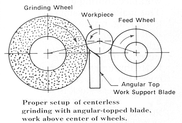
In thrufeed centerless OD grinding the workpiece passes between two wheels, a grinding wheel and a regulating wheel (as illustrated in the diagram below). Both wheels rotate in the same direction, but at much different speeds. The purpose of the grinding wheel is to remove material from the workpiece and improve part OD quality. The regulating wheel acts like a brake, controlling the rotational speed and thrufeed rate of the workpeice. An angular-topped workrest blade supports the workpiece as it passes through the grinder between the grinding and regulating wheels.


The workpiece passes between two wheels, a grinding wheel and a regulating wheel.


The abrasive types used in the grinding wheel are determined by the part material to be ground. Aluminum oxide, ceramic aluminum oxide and CBN grains are typically used to grind ferrous materials. Silicon carbide and diamond grains are typically used on non-ferrous materials. These grains are used in vitrified or resin bonds to make a grinding wheel. Generally vitrified bonds are used to grind “weak” configured parts that may deform when high grind force is applied. Resin bond grind wheels are used to grind stronger parts like bars or solid rollers.

Regulating wheels are made in rubber, plastic or vitrified bonds. Some applications like tapered rollers use special shaped, hardened steel regulating wheels.

Machine Setup Parameters

  1. Top angle on workrest blade.
  2. Relationship of the part center height above the wheel’s centerline dimension with the regulating wheel diamond dresser offset dimension.
  3. The regulating wheel angle of inclination or work feed angle to the regulating wheel dresser angle.
  4. Entrance/exit guide alignment.

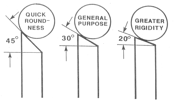
The top angle on the workrest blade helps with the rounding action of the part. With increased angle, quicker rounding occurs, but it also weakens the blade rigidity. The most common top angle used in centerless grinding is 30 degrees. As the diagram below indicates, lower angles are used when grinding heavy workpieces, which help minimize vibration. Workrest top angles typically range from 45 degrees down to 20 degrees. Generally speaking, 30 degrees is a good starting point for the majority of parts to be thrufed centerless ground.


The top angle on the workrest blade helps with the rounding action of the part.


A majority of centerless grinders are set up with the work center height above the centerline of both wheels. There are some applications like bar grinding that set up the bar center below the centerline of the wheels to keep bar vibration low during the grinding process. We will focus on setups with the work center above the centerline of the wheels, which is commonly called “work height above center.” Part diameters 1½" or less should have the height above center dimension set at half the part diameter. Parts greater than 1½" should be proportionally less for stability reasons. The purpose of the truing device on the regulating wheel is to have the diamond follow a similar line of contact to the wheel that the parts will follow. This will allow parts to enter and exit the grind zone in a straight line. So there is an important relationship that ties the work height above center dimension to the regulating wheel diamond offset setting. (See images below.)


There is an important relationship that ties the work height above center dimension to the regulating wheel diamond offset setting.The purpose of the truing device on the regulating wheel is to have the diamond follow a similar line of contact to the wheel that the parts will follow.


Typically the diamond offset is set slightly less than the workpiece height above center dimension. It is key to understand that this relationship influences the grind pattern and part contact to the grinding wheel as parts pass through the grinder. It is very important to calculate the ratio of the regulating wheel diameter to the workpeice diameter, or D/d. “D” is the regulating wheel diameter and “d” is the workpeice diameter. Once you know this ratio, then you can use the “Truing Setting” chart (below) to determine the correct truing angle and diamond offset.

The “Truing Setting” chart determines the correct truing angle and diamond offset.

The regulating wheel angle of inclination typically is in the +1 degree to +3 degree range. This angle, along with regulating wheel speed (RPMs), determines the part thrufeed rate in inches per minute. This setting also affects the distance a part will travel in one workpiece revolution. A lower angle means a shorter travel distance and this affects grind force on the workpeice. So you can affect how a grinding wheel performs by changing regulating wheel inclination and regulating wheel RPMs. Parts that have a high diameter-to-length ratio, such as bearing rings, should have a lower regulating wheel angle of inclination to help keep the parts stable as they travel through the grind zone. Proper settings allow the workpieces to smoothly enter and exit the grind zone.

Typically there are adjustable guides on the entrance and exit sides of the grind machine. The purpose of the guides is to align the workpeices as the wheel goes in and comes out of the grind zone. (See diagram below.) It is important to correctly align the guides located on the regulating wheel side. The workpeices should smoothly transition between guides and regulating wheel. Even a slight “bump” during the transition can cause a defect to be ground into your parts.


Typically there are adjustable guides on the entrance and exit sides of the grind machine.


Proper guide alignment is important to avoid your parts from having a “barrel” or “hour glass” diameter across the part length. The illustration below shows how misaligned guides could affect part quality.


This illustration shows how misaligned guides could affect part quality.


Be sure to inspect all the tooling used in the centerless grinder, and make sure all tooling is in good condition. You can have a good machine setup, but if the diamond tools are worn, they will cause dull dress condition on your wheels and generate poor part quality. Paying close attention to your tooling condition and machine setup will ensure that your grinder will produce excellent part quality at low manufacturing costs.

Related Glossary Terms

  • abrasive

    abrasive

    Substance used for grinding, honing, lapping, superfinishing and polishing. Examples include garnet, emery, corundum, silicon carbide, cubic boron nitride and diamond in various grit sizes.

  • aluminum oxide

    aluminum oxide

    Aluminum oxide, also known as corundum, is used in grinding wheels. The chemical formula is Al2O3. Aluminum oxide is the base for ceramics, which are used in cutting tools for high-speed machining with light chip removal. Aluminum oxide is widely used as coating material applied to carbide substrates by chemical vapor deposition. Coated carbide inserts with Al2O3 layers withstand high cutting speeds, as well as abrasive and crater wear.

  • centerless grinding

    centerless grinding

    Grinding operation in which the workpiece rests on a knife-edge support, rotates through contact with a regulating or feed wheel and is ground by a grinding wheel. This method allows grinding long, thin parts without steady rests; also lessens taper problems. Opposite of cylindrical grinding. See cylindrical grinding; grinding.

  • centers

    centers

    Cone-shaped pins that support a workpiece by one or two ends during machining. The centers fit into holes drilled in the workpiece ends. Centers that turn with the workpiece are called “live” centers; those that do not are called “dead” centers.

  • cubic boron nitride ( CBN)

    cubic boron nitride ( CBN)

    Crystal manufactured from boron nitride under high pressure and temperature. Used to cut hard-to-machine ferrous and nickel-base materials up to 70 HRC. Second hardest material after diamond. See superabrasive tools.

  • feed

    feed

    Rate of change of position of the tool as a whole, relative to the workpiece while cutting.

  • grinding

    grinding

    Machining operation in which material is removed from the workpiece by a powered abrasive wheel, stone, belt, paste, sheet, compound, slurry, etc. Takes various forms: surface grinding (creates flat and/or squared surfaces); cylindrical grinding (for external cylindrical and tapered shapes, fillets, undercuts, etc.); centerless grinding; chamfering; thread and form grinding; tool and cutter grinding; offhand grinding; lapping and polishing (grinding with extremely fine grits to create ultrasmooth surfaces); honing; and disc grinding.

  • grinding wheel

    grinding wheel

    Wheel formed from abrasive material mixed in a suitable matrix. Takes a variety of shapes but falls into two basic categories: one that cuts on its periphery, as in reciprocating grinding, and one that cuts on its side or face, as in tool and cutter grinding.

  • inches per minute ( ipm)

    inches per minute ( ipm)

    Value that refers to how far the workpiece or cutter advances linearly in 1 minute, defined as: ipm = ipt 5 number of effective teeth 5 rpm. Also known as the table feed or machine feed.

  • outer diameter ( OD)

    outer diameter ( OD)

    Dimension that defines the exterior diameter of a cylindrical or round part. See ID, inner diameter.

  • truing

    truing

    Using a diamond or other dressing tool to ensure that a grinding wheel is round and concentric and will not vibrate at required speeds. Weights also are used to balance the wheel. Also performed to impart a contour to the wheel’s face. See dressing.