One of the challenges of metalcutting—whether it is interrupted or continuous—is measuring, and therefore monitoring, the temperature of the tool/chip interface. This challenge assumes greater urgency with the desire to develop smart cutting tools.
Higher cutting temperatures can lead not only to more rapid tool wear but to tool failures or even metal fires. Understanding and controlling these temperatures is essential for developing better machining processes.
A team of researchers at the University of Wisconsin-Madison has addressed the challenge by using thermocouples embedded in a cutting insert’s coating to measure the tool/chip interface temperature.
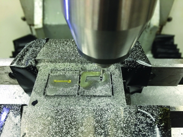
Mask fabrication for thin-film thermocouple sputtering (physical vapor deposition). Image courtesy of Sinan Kesrikliolu.
Frank Pfefferkorn, associate professor of mechanical engineering at the university and director of the Manufacturing Systems Engineering Program, leads the team. He said team members worked with standard tungsten-carbide inserts and conducted the first tests on AISI 12L14 steel. They used micromachined stencils to sputter the thin-film thermocouples onto the inserts, then coated the junction with a protective layer.
“These tests let us observe the influence that both cutting speed and cooling intervals have on the tool/chip interface temperature,” Pfefferkorn said. “Part of the challenge overall is to achieve response times that are fast enough that the temperature sensor can capture the data.”
Very fast measurement response times are made possible by embedding the thermocouples inside the tool coating, where it is a mere 1.3μm below the tool/chip interface.
He added that the inserts must be fabricated in a way that the coatings do not delaminate when machining steels of low-to-moderate hardness at a speed range beyond which a built-up edge forms.
The researchers initially selected relatively large thermocouple junctions (100μm × 100μm) for the test inserts. These junctions could be produced with sputtering through masks, and the masks could be fabricated with micro-endmilling rather than more complicated processes.
The study demonstrates that the temperature for the tool/chip interface is lower for interrupted cutting than for continuous cutting. Noncutting periods decrease the overall heat input, allowing the tool to dissipate the heat.
“We chose this approach to instrumenting a cutting insert to make it easier to take these findings out of the lab and apply them to the production environment,” Pfefferkorn said. “Improved capabilities for monitoring temperature will help us look further into the impact of temperature on milling and tool wear. They will enable us to improve the various cooling methods that affect the interface temperature and actively control it.”
For more information about manufacturing research at the University of Wisconsin-Madison, visit lamsml.engr.wisc.edu or call (608) 263-2668.
Related Glossary Terms
- built-up edge ( BUE)
built-up edge ( BUE)
1. Permanently damaging a metal by heating to cause either incipient melting or intergranular oxidation. 2. In grinding, getting the workpiece hot enough to cause discoloration or to change the microstructure by tempering or hardening.
- cutting speed
cutting speed
Tangential velocity on the surface of the tool or workpiece at the cutting interface. The formula for cutting speed (sfm) is tool diameter 5 0.26 5 spindle speed (rpm). The formula for feed per tooth (fpt) is table feed (ipm)/number of flutes/spindle speed (rpm). The formula for spindle speed (rpm) is cutting speed (sfm) 5 3.82/tool diameter. The formula for table feed (ipm) is feed per tooth (ftp) 5 number of tool flutes 5 spindle speed (rpm).
- gang cutting ( milling)
gang cutting ( milling)
Machining with several cutters mounted on a single arbor, generally for simultaneous cutting.
- hardness
hardness
Hardness is a measure of the resistance of a material to surface indentation or abrasion. There is no absolute scale for hardness. In order to express hardness quantitatively, each type of test has its own scale, which defines hardness. Indentation hardness obtained through static methods is measured by Brinell, Rockwell, Vickers and Knoop tests. Hardness without indentation is measured by a dynamic method, known as the Scleroscope test.
- milling
milling
Machining operation in which metal or other material is removed by applying power to a rotating cutter. In vertical milling, the cutting tool is mounted vertically on the spindle. In horizontal milling, the cutting tool is mounted horizontally, either directly on the spindle or on an arbor. Horizontal milling is further broken down into conventional milling, where the cutter rotates opposite the direction of feed, or “up” into the workpiece; and climb milling, where the cutter rotates in the direction of feed, or “down” into the workpiece. Milling operations include plane or surface milling, endmilling, facemilling, angle milling, form milling and profiling.
Author

Robert Weinstein is a contributing editor for CTE. Contact him at (732) 583-7171 or [email protected].