Tool grinder Jim Clark employs the ANCA CNC tool grinding machine at Hamill Manufacturing to create custom geometry on an endmill. Hamill manufactures and modifies tools in-house to maximize efficiency when machining complex parts for military applications.
Creating awareness about productivity-boosting machining technologies and implementing them are playing a major role in making military parts.
Technology transfer is a two-way street. For example, technology NASA developed for space exploration often is adapted by the private sector for terrestrial use, while technological advances made for commercial purposes are being targeted for implementation by the Department of Defense and part manufacturers serving the defense industry. This two-way technology transfer can help increase the nation’s industrial competitiveness, create jobs and improve the balance of trade. In the case of making military parts, the goal of commercial-to-government transfer is to reduce or contain costs by enhancing manufacturing productivity while providing the military with the weapons needed to effectively battle enemies.
One organization helping to facilitate that aim is the National Center for Defense Manufacturing and Machining, Latrobe, Pa. “A lot of the advances in technology come from the commercial sector,” said Ralph Resnick, chief technology officer for NCDMM. “It is up to organizations like NCDMM to help educate the government base on what these commercial processes and technologies are.”
Courtesy of Siemens
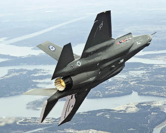
The F-35 Lightning II, or Joint Strike Fighter, is one military program that requires advanced manufacturing technologies to efficiently produce all of the needed components.
He noted, however, that because the military needs consistently reliable products, the manufacturing processes for creating those products need to be consistent and validated. That can make implementation of innovative manufacturing solutions a slow process. “The military is very careful about making changes and sometimes this can be a deterrent to change,” Resnick said. “It is the responsibility of organizations like mine to be able to manage that change process and to appropriately transition new capabilities. We need to demonstrate and validate those capabilities so we can get them through the qualification process and subsequently improve manufacturing, which has implications of cost reduction and improved productivity.”
Presented here are several NCDMM projects that implement advanced manufacturing technology, including laser-based measurement, ultrasonic machining and gundrilling.
Out with the Blue
The propulsion drive shafts of Navy submarines, ships and aircraft carriers require maintenance about every 2 years. That involves dry docking the ship or submarine at a Navy shipyard, removing the shaft, inspecting it for wear, filling in any worn areas using additive techniques and then removing excess material on a lathe and with a hand-held grinder. The shafts measure up to 30 " in diameter and 60 ' or more in length. The current method for inspecting a shaft taper, which has been the accepted practice for 50 years, utilizes a bluing fit.
Resnick noted that there are a total of five ring gages used by the U.S. shipyard community for inspecting such large shafts. Each gage weighs 500 to 600 lbs. and is positioned onto a shaft using a sledge hammer with a specific weight and a prescribed number of hammer blows. Then the gage, which has a bluing die applied to its contact surface, is removed and a group of inspectors collectively determine the percentage of bluing transferred from the gage to the shaft, with a good shaft having at least 80 percent of the die. “If the shaft needs additional machining, it’s reinstalled on the machine tool and the process is reiterated,” Resnick said. “It’s very time-consuming and very archaic.”
The inspection process takes about 72 man-hours. “The standard rule of thumb on what are called hotel services, or write-up expenses while in dry dock, is that they cost $250,000 a day minimum,” said Sean Krieger, project engineer with a specialty in repair technology at the Applied Research Laboratory at Penn State. “So the clock is ticking the minute that submarine or ship arrives in the dry dock for refurbishment work.”
The Pearl Harbor Navy Shipyard asked ARL to help improve its metrology processes, including shaft taper inspection. Before that initial project ended, ARL recommended using a Laser Tracker from laser measurement system provider Faro Technologies Inc., Lake Mary, Fla., to do the inspection. Next, NCDMM became involved in the improvement process and concurred that on-machine, laser-measurement assessment of the shafts was an important step forward.
Courtesy of Faro Technologies
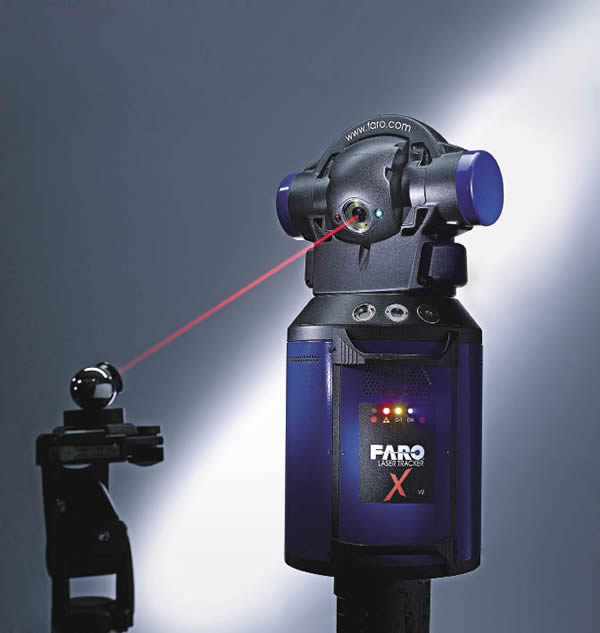
A Laser Tracker from Faro Technologies can measure a component, such as a propulsion drive shaft, anywhere and in any orientation.
A Laser Tracker can inspect a shaft anywhere and in any orientation, eliminating the need to remove the shaft from the lathe and position the gage using a crane, according to Chuck Pfeffer, director of product development for Faro, who’s based in Kennett Square, Pa. He explained that to scan the taper section, which measures about 4 ' long by 2 ' in diameter, an operator first scans half of it from one vantage point by sliding a laser-following probe along the surface of the shaft taper, recording the data as the probe moves, scanning the other side and then tying the two coordinate systems together to provide a single set of scan data. Software, available from multiple developers, allows a user to collect thousands of data points and compare them to a CAD model of the shaft or gage. The software also generates a color map report and a statistical report.
“Pretty much in real time, you can see the data compared to the CAD model on the screen, and analysis tools tell you what percentage is within a certain tolerance to simulate the bluing,” Pfeffer said. “We were trying to get as close a comparison to the gage as we could.”
He added that laser measurement provided a numerical value for the amount of material that would have been interfering with the gage, as well as the gage’s distance from low, worn areas on the shaft. “You didn’t just get a shade of blue, you got a number.”
Laser-based measurement also quickened the machining process. “They tended to take off very little material at a time when they were doing the gage process because they were not that confident in what they were doing based on the feedback from the gage,” Pfeffer said. “With the Laser Tracker, you could take off more material at once, being confident that you knew how much to remove, reducing some of the iterations.”
The prove-out inspections, which were performed at the Norfolk, Portsmouth, Puget Sound and Pearl Harbor Navy Shipyards, determined the proposed Laser Tracker method would take 24 man-hours, saving 48 man-hours per shaft taper. Based on an average shipyard quantity of three shafts per year at each of the six shipyards, the projected 10-year savings equates to $1,962,000, according to NCDMM.
The prove-out process ended March 2008 and the Navy is continuing to evaluate the laser technique. “They double and triple check everything,” Krieger said. “By having outside consultants come in and conduct this evaluation, it opened up their eyes and allowed them to say, ‘Yes, we’ll seriously consider it,’ but it did need to get to a program called ‘cumbersome work practices’ to be fully considered for implementation.”
NCDMM remains optimistic. “We’re hoping that within the next year we will see implementation of the technique,” Resnick said.
Even if the shipyards don’t eliminate use of the ring gage for final inspection, they can still incorporate laser measurement to reduce the total cycle time. “Using it as an in-process tool to get a shaft built right will save most of the time and money,” Pfeffer said, adding that sharing the lessons learned and applying them to other Navy projects would indicate a successful project. “Replacing the gage would be a bonus, but it was very successful for the Navy just to understand what they can use this tool for.”
Machining Composites
There’s usually more than one way to machine part features. That’s the case for tapered cooling holes and seal slots in ceramic matrix composite materials for military aerospace components. CMC is desirable for aerospace applications because it’s a low-weight, high-strength, high temperature-resistant material. However, machining it isn’t so desirable. That’s because CMC is a sintered, dense material that has a laminate structure with four to 12 plies (eight-ply being the most common) and silicon-carbide fibers woven together.
NCDMM has been optimizing machining processes for CMC materials but during an investigation of conventional milling of 0.030 "-wide × 0.150 "- to 0.200 "-deep seal slots for a military aerospace application found that conventional processes took an inordinate amount of time. NCDMM enlisted the assistance of one of its alliance partners, The Ex One Co. LLC, Irwin, Pa., to examine laser and ultrasonic machining of the slots with the equipment the company builds and markets and also uses for its job shop services. Ultrasonic machining uses a vibrating tool to erode the desired shape into the workpiece material.
The time to ultrasonically machine a 3 "-long, 0.150 "-deep, C-shaped slot was 30 minutes, whereas milling required 5 to 10 hours to produce the same slot and consumed five to 10 cutters. “The tooling cost alone was exorbitant but the machining time on top of that was ridiculous,” said Ex One’s Corporate Director of Technology Randy Gilmore.
Drilling cooling holes posed similar problems. Each hole is tapered, having a 0.015 " diameter for air entry and a 0.025 " diameter for air exit, to enhance cooling characteristics by enabling air to spread out as it exits the hole and drag more heat away. In addition, the holes are at a 25° angle to the surface of the material for better cooling. Gilmore noted that drilling CMC is a slow process that requires multiple drill bits to complete each hole, and one part may have up to 300 holes.
Ex One was able to laser machine an acceptable hole—no delamination, cracking or fiber or bond coat damage—in about 5 minutes, but only with a laser that provides an ultrashort pulse duration of 10 picoseconds or less. “We also drilled some holes in the nanosecond and millisecond ranges,” Gilmore said. “As we got into those longer pulse durations, we definitely damaged the material.”
Laser machining is not feasible for machining the seal slots because of the difficulty in producing a flat bottom in the slot and—more importantly—the relatively large amount of material that must be removed.
Although ultrasonically drilling a hole takes about 30 minutes, up to 30 ultrasonic tools can be ganged, enabling 30 holes to be drilled in 30 minutes, according to Gilmore. He explained that Ex One’s ultrasonic system incorporates projection machining, where the vibrating tool, called a sonotrode, never touches the workpiece but rather abrasive particles suspended in a liquid are projected across the gap between the tool and workpiece, striking and eroding the negative shape of the tool into the workpiece. The sonotrode vibrates at a nominal frequency of 20 kHz, and the tool tip is vibrating in an amplitude, or stroke, of ±0.001 ". The slurry contains a liquid carrier with abrasive particles suspended in it, as well as lubricants and rust inhibitors because the sonotrodes are typically made of tool steel.
Numerous abrasives are available. For the CMC application, Ex One applied 320-mesh silicon carbide. Gilmore noted that the company used standard ultrasonic machining, which does not damage CMC, but custom tools were needed based on part geometry.
NCDMM stated that with the knowledge gained through the testing of these various machining methods, optimized conventional milling is appropriate for some applications and ultrasonic machining was determined to be applicable for machining tapered cooling holes, seal slots and other part features with similar characteristics. “Because we were able to use the customer’s shapes and materials in our demonstration project on the contract for NCDMM,” Gilmore said, “it was an easy segue for the customer to go directly into utilizing our services to make the actual engine components.” The NCDMM evaluation project has led to subsequent production evaluation contracts for Ex One.
Drilling Deep
Military parts come in all shapes, sizes and workpiece materials, including thick ones made of difficult-to-machine nickel-base alloys. But that doesn’t necessary mean a new machining technology is needed to produce a difficult-to-machine workpiece. Instead, Hamill Manufacturing Co., Trafford, Pa., needed to identify the appropriate traditional cutting tool to efficiently drill approximately 600 through-holes about 3⁄8 " in diameter in four 4½ "-thick Inconel heat exchanger components for the Navy. Hole tolerance was ±0.001 ".
The company had experience drilling Inconel up to 2 " thick and considered drilling and reaming the holes using the same parameters when machining the thicker Inconel parts. However, that meant more than 200 hours to produce each part and if a single hole was out of specification—hopefully not the last one—Hamill would have to scrap the part. “We bid the job knowing it was going to take a long period of time, but it was taking longer than we expected,” said Glenn Skena, manager of methods engineering for Hamill.
Being an NCDMM member, Hamill, which currently produces 60 percent of its parts for the Navy, contacted the center to see if a solution could be found. “We’ve had at least three projects with NCDMM over the years,” Skena said.
Courtesy of Bill Kennedy
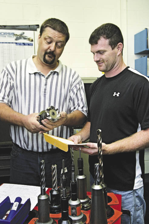
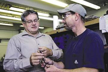
Tooling Coordinator Dave Karpinski (left) works with Brian Bearley, CNC programmer, to optimize cutting tools for an application at Hamill Manufacturing.
Courtesy of NCDMM
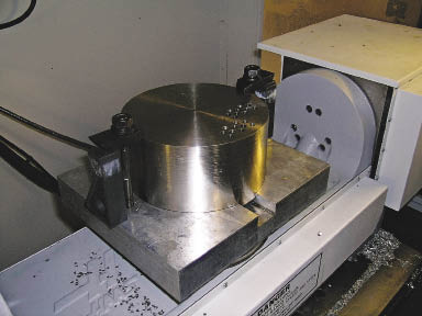
NCDMM performed “proof-of-concept” drilling tests on a 4”-thick Inconel sample to help Hamill Manufacturing reduce its machining time by 50 percent.
NCDMM conducted machining tests on a sample Inconel workpiece using a Haas vertical machining center and determined a special Star Cutter gundrill with application-specific point geometry produced the best results. According to NCDMM, gundrills are designed to produce deep, straight and accurate holes. “The deeper the hole is, the harder it is to keep the tool straight,” said Dave Karpinski, Hamill’s tooling coordinator.
In addition to having a high-quality tool, the best results occurred when the gundrill entered the pilot hole rotating counterclockwise and then changed to clockwise rotation when the actual drilling began. Because there’s only a minimal amount of clearance as the gundrill enters the hole, that procedure prevents the tool from rubbing the workpiece, Karpinski explained.
Retracting the drill from the hole with the machine spindle turned off also proved beneficial. “If you’re retracting the gundrill and the spindle is on, you’ll turn that gundrill into a pretzel,” Karpinski said.
Karpinski noted that after NCDMM developed the gundrilling process, Hamill optimized the process to make it more efficient. “They pretty much kicked the door down for us to get through the rough spots,” he said.
Although Hamill is accustomed to designing and grinding specials for its challenging applications, the company was unable to develop the gundrill in-house. “In this case, we used NCDMM as an extension of Dave due to the work load here and time constraints,” said John Dalrymple, company president.
Dalrymple added that although gundrilling is typically done on a dedicated gundrill machine, the process was developed for use on a horizontal mill, partly because of the coolant application requirements.
To apply the proper 10 percent coolant concentration and 1,000-psi pressure for the through-coolant gundrill, Hamill purchased a high-pressure coolant system, which cost about $12,000. NCDMM estimated that gundrilling reduced holemaking time by 50 percent or more, for a savings of $33,360.
“If it’s competitively bid and we got the job, then we’re not going to get anymore money for it,” Skena said. “But if we can figure out a way to spend some money, do it a little cheaper and save some time and money, that’s an advantage.”
The process change didn’t require customer approval, and Hamill continues to apply gundrills for other holemaking operations in various materials, including Inconel and stainless steel.
According to Skena, the Navy is looking for the best price and usually the lowest bid gets the job, but the bidding process is also delivery-driven. If the lowest bid can’t deliver on time, “sometimes they’ll pay 5 to 10 percent more to get the delivery they need,” he said.
Hamill employs 115 workers and operates three shifts.
Culture Issues
Transitioning technology from the commercial sector to the military requires more than proving the technology works and meets the requirements of the qualification process. The military establishment must also be educated about the benefits and implementation of the technology.
Part of that education is the technology training NCDMM provides. As an example, Penn State ARL’s Krieger noted that as soon as the laser measurement project was completed, NCDMM conducted 5-axis machining and NC programming classes at the Pearl Harbor Navy Shipyard to fill knowledge gaps.
“Our project strategy extends beyond doing the technical development, technical validation and technical demonstration into technical training,” NCDMM’s Resnick said.
Courtesy of Bill Kennedy
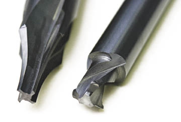
Hamill Manufacturing President John Dalrymple (left) discusses the geometry of a custom drill ground by Jim Clark on the facility’s ANCA CNC tool grinder. Inset: In-house CNC tool grinding capability enables Hamill Manufacturing to quickly make or modify tools, such as these custom endmills, to produce complex features on military parts.
Compared to veteran workers who are more accustomed to performing functions in a certain way, younger workers are more excited to incorporate changes that create improvements, Resnick noted. In addition, younger workers are often familiar with newer technologies, such as social networking, which can facilitate supply chain interaction. To leverage social networks, NCDMM is developing a software tool called VOICE (Virtual Opportunity Interchange CEnter). “We’re utilizing some methodologies that have come out of the social networking communities and are essentially developing a private business community similar to Facebook and eHarmony,” Resnick said.
That should only add to the significant role organizations like NCDMM play in transferring productivity-enhancing manufacturing technology from the commercial sector to the military base. “Once it comes to us from NCDMM, it’s already been qualified that the military is looking for a better way to do it,” Ex One’s Gilmore said. “We’re pulled in rather than pushing our technology on them.” CTE
About the Author: Alan Richter is editor of Cutting Tool Engineering, having joined the publication in 2000. Contact him at (847) 714-0175 or [email protected].
Taking the plunge
When it comes to cost reduction for machined parts, military customers are no different from other ones—they want it. “But equally important is the quality of the product, the integrity of the product,” said Bob Perkins, president of PDS Industries Inc., Irwin, Pa.
PDS had previously machined RHD plates for a defense application and the parts manufacturer had to reduce its price to obtain another order. That required PDS to reduce its manufacturing cost, so being a member of the National Center for Defense Manufacturing and Machining consortium, PDS contacted the center for assistance in reducing machine cycle time.
Previously, PDS applied three tools for roughing the 304 stainless steel parts using a side milling technique at slower machining parameters to minimize chatter and prolong cutter life, which took about 4.85 hours. Upon review, NCDMM determined that plunge milling during roughing, which directed the cutting force into the spindle mass, reduced cycle time to 1.5 hours. That resulted in a $20,000 savings for the 70-part run.
“With side milling, which pushes at the side of the spindle, we couldn’t take the DOC that we’re able to take with the plunge milling approach,” said Bill Krause, director of engineering and estimating for PDS. He noted that the finishing operation remained the same. “They felt our finishing approach was as good as we could get.”
In addition to generating the necessary plunge milling program and speeds and feeds, NCDMM selected two cutting tools for roughing: 1.5 "- and 2.5 "-dia. Z-axis plunge milling cutters from Kennametal tooled with grade-KC935M inserts. PDS ran the 1.5 " cutters at 1,273 rpm, a 180-ipm feed and a 0.200 " DOC, and the 2.5 " cutter at 764 rpm, a 28.0-ipm feed and a 0.330 " DOC. The plates have some complex geometries, including deep pockets, and the 1.5 "-dia. mill requires cutting at up to a 4:1 length-to-diameter ratio.
The plunge mills cost about 50 percent more than the side milling tools, but in addition to reducing cycle time, plunge milling generates smaller chips and minimizes chip packing in the flutes, according to Krause. “Plunge milling lets the tool clean itself quicker,” he said, noting that the parts were cut dry with compressed air, which helped evacuate chips.
Because applying the plunge mills only required a programming change, PDS was able to run the parts on its existing Haas vertical machining centers. In addition to being able to plunge mill future RHD plate jobs, PDS is using the technique for other suitable applications.
—A. Richter
Contributors
Applied Research Laboratory at Penn State
(814) 865-6531
www.arl.psu.edu
The Ex One Co. LLC
(724) 863-9663
www.exone.com
Faro Technologies Inc.
(800) 736-2771
www.faro.com
Hamill Manufacturing Co.
(724) 744-2131
www.hamillmfg.com
National Center for Defense Manufacturing and Machining
(724) 539-8811
www.ncdmm.org
PDS Industries Inc.
(724) 863-1100
www.pdsindustries.com
Contact Details
Related Glossary Terms
- abrasive
abrasive
Substance used for grinding, honing, lapping, superfinishing and polishing. Examples include garnet, emery, corundum, silicon carbide, cubic boron nitride and diamond in various grit sizes.
- alloys
alloys
Substances having metallic properties and being composed of two or more chemical elements of which at least one is a metal.
- centers
centers
Cone-shaped pins that support a workpiece by one or two ends during machining. The centers fit into holes drilled in the workpiece ends. Centers that turn with the workpiece are called “live” centers; those that do not are called “dead” centers.
- chatter
chatter
Condition of vibration involving the machine, workpiece and cutting tool. Once this condition arises, it is often self-sustaining until the problem is corrected. Chatter can be identified when lines or grooves appear at regular intervals in the workpiece. These lines or grooves are caused by the teeth of the cutter as they vibrate in and out of the workpiece and their spacing depends on the frequency of vibration.
- chuck
chuck
Workholding device that affixes to a mill, lathe or drill-press spindle. It holds a tool or workpiece by one end, allowing it to be rotated. May also be fitted to the machine table to hold a workpiece. Two or more adjustable jaws actually hold the tool or part. May be actuated manually, pneumatically, hydraulically or electrically. See collet.
- clearance
clearance
Space provided behind a tool’s land or relief to prevent rubbing and subsequent premature deterioration of the tool. See land; relief.
- composites
composites
Materials composed of different elements, with one element normally embedded in another, held together by a compatible binder.
- computer numerical control ( CNC)
computer numerical control ( CNC)
Microprocessor-based controller dedicated to a machine tool that permits the creation or modification of parts. Programmed numerical control activates the machine’s servos and spindle drives and controls the various machining operations. See DNC, direct numerical control; NC, numerical control.
- computer-aided design ( CAD)
computer-aided design ( CAD)
Product-design functions performed with the help of computers and special software.
- conventional milling ( up milling)
conventional milling ( up milling)
Cutter rotation is opposite that of the feed at the point of contact. Chips are cut at minimal thickness at the initial engagement of the cutter’s teeth with the workpiece and increase to a maximum thickness at the end of engagement. See climb milling.
- coolant
coolant
Fluid that reduces temperature buildup at the tool/workpiece interface during machining. Normally takes the form of a liquid such as soluble or chemical mixtures (semisynthetic, synthetic) but can be pressurized air or other gas. Because of water’s ability to absorb great quantities of heat, it is widely used as a coolant and vehicle for various cutting compounds, with the water-to-compound ratio varying with the machining task. See cutting fluid; semisynthetic cutting fluid; soluble-oil cutting fluid; synthetic cutting fluid.
- cutting force
cutting force
Engagement of a tool’s cutting edge with a workpiece generates a cutting force. Such a cutting force combines tangential, feed and radial forces, which can be measured by a dynamometer. Of the three cutting force components, tangential force is the greatest. Tangential force generates torque and accounts for more than 95 percent of the machining power. See dynamometer.
- endmill
endmill
Milling cutter held by its shank that cuts on its periphery and, if so configured, on its free end. Takes a variety of shapes (single- and double-end, roughing, ballnose and cup-end) and sizes (stub, medium, long and extra-long). Also comes with differing numbers of flutes.
- feed
feed
Rate of change of position of the tool as a whole, relative to the workpiece while cutting.
- flat ( screw flat)
flat ( screw flat)
Flat surface machined into the shank of a cutting tool for enhanced holding of the tool.
- flutes
flutes
Grooves and spaces in the body of a tool that permit chip removal from, and cutting-fluid application to, the point of cut.
- gang cutting ( milling)
gang cutting ( milling)
Machining with several cutters mounted on a single arbor, generally for simultaneous cutting.
- grinding
grinding
Machining operation in which material is removed from the workpiece by a powered abrasive wheel, stone, belt, paste, sheet, compound, slurry, etc. Takes various forms: surface grinding (creates flat and/or squared surfaces); cylindrical grinding (for external cylindrical and tapered shapes, fillets, undercuts, etc.); centerless grinding; chamfering; thread and form grinding; tool and cutter grinding; offhand grinding; lapping and polishing (grinding with extremely fine grits to create ultrasmooth surfaces); honing; and disc grinding.
- grinding machine
grinding machine
Powers a grinding wheel or other abrasive tool for the purpose of removing metal and finishing workpieces to close tolerances. Provides smooth, square, parallel and accurate workpiece surfaces. When ultrasmooth surfaces and finishes on the order of microns are required, lapping and honing machines (precision grinders that run abrasives with extremely fine, uniform grits) are used. In its “finishing” role, the grinder is perhaps the most widely used machine tool. Various styles are available: bench and pedestal grinders for sharpening lathe bits and drills; surface grinders for producing square, parallel, smooth and accurate parts; cylindrical and centerless grinders; center-hole grinders; form grinders; facemill and endmill grinders; gear-cutting grinders; jig grinders; abrasive belt (backstand, swing-frame, belt-roll) grinders; tool and cutter grinders for sharpening and resharpening cutting tools; carbide grinders; hand-held die grinders; and abrasive cutoff saws.
- gundrill
gundrill
Self-guided drill for producing deep holes with good accuracy and fine surface finish. Has coolant passages that deliver coolant to the tool/workpiece interface at high pressure.
- gundrilling
gundrilling
Drilling process using a self-guiding tool to produce deep, precise holes. High-pressure coolant is fed to the cutting area, usually through the gundrill’s shank.
- laser machining
laser machining
Intensified, pulsed beams of light generated by lasers—typically carbon dioxide or neodium-doped yttrium aluminum garnet (Nd:YAG)—that drill, weld, engrave, mark, slit and caseharden. Usually under CNC, often at both high cutting rates (100 linear in./sec.) and high power (5kW or more). Lasers also are used in conjunction with in-process quality-control monitoring systems allowing measuring accuracies of 0.00001".
- lathe
lathe
Turning machine capable of sawing, milling, grinding, gear-cutting, drilling, reaming, boring, threading, facing, chamfering, grooving, knurling, spinning, parting, necking, taper-cutting, and cam- and eccentric-cutting, as well as step- and straight-turning. Comes in a variety of forms, ranging from manual to semiautomatic to fully automatic, with major types being engine lathes, turning and contouring lathes, turret lathes and numerical-control lathes. The engine lathe consists of a headstock and spindle, tailstock, bed, carriage (complete with apron) and cross slides. Features include gear- (speed) and feed-selector levers, toolpost, compound rest, lead screw and reversing lead screw, threading dial and rapid-traverse lever. Special lathe types include through-the-spindle, camshaft and crankshaft, brake drum and rotor, spinning and gun-barrel machines. Toolroom and bench lathes are used for precision work; the former for tool-and-die work and similar tasks, the latter for small workpieces (instruments, watches), normally without a power feed. Models are typically designated according to their “swing,” or the largest-diameter workpiece that can be rotated; bed length, or the distance between centers; and horsepower generated. See turning machine.
- machining center
machining center
CNC machine tool capable of drilling, reaming, tapping, milling and boring. Normally comes with an automatic toolchanger. See automatic toolchanger.
- metrology
metrology
Science of measurement; the principles on which precision machining, quality control and inspection are based. See precision machining, measurement.
- milling
milling
Machining operation in which metal or other material is removed by applying power to a rotating cutter. In vertical milling, the cutting tool is mounted vertically on the spindle. In horizontal milling, the cutting tool is mounted horizontally, either directly on the spindle or on an arbor. Horizontal milling is further broken down into conventional milling, where the cutter rotates opposite the direction of feed, or “up” into the workpiece; and climb milling, where the cutter rotates in the direction of feed, or “down” into the workpiece. Milling operations include plane or surface milling, endmilling, facemilling, angle milling, form milling and profiling.
- milling machine ( mill)
milling machine ( mill)
Runs endmills and arbor-mounted milling cutters. Features include a head with a spindle that drives the cutters; a column, knee and table that provide motion in the three Cartesian axes; and a base that supports the components and houses the cutting-fluid pump and reservoir. The work is mounted on the table and fed into the rotating cutter or endmill to accomplish the milling steps; vertical milling machines also feed endmills into the work by means of a spindle-mounted quill. Models range from small manual machines to big bed-type and duplex mills. All take one of three basic forms: vertical, horizontal or convertible horizontal/vertical. Vertical machines may be knee-type (the table is mounted on a knee that can be elevated) or bed-type (the table is securely supported and only moves horizontally). In general, horizontal machines are bigger and more powerful, while vertical machines are lighter but more versatile and easier to set up and operate.
- numerical control ( NC)
numerical control ( NC)
Any controlled equipment that allows an operator to program its movement by entering a series of coded numbers and symbols. See CNC, computer numerical control; DNC, direct numerical control.
- plunge milling
plunge milling
Highly productive method of metal removal in which an axial machining operation is performed in a single tool sequence. The tool makes a series of overlapping, drill-like plunges to remove part of a cylindrical plug of material one after another. Because of the increased rigidity of a Z-axis move, the tool can cover a large cross-section of material.
- tolerance
tolerance
Minimum and maximum amount a workpiece dimension is allowed to vary from a set standard and still be acceptable.
- ultrasonic machining
ultrasonic machining
Material-removal operation in which an abrasive slurry flows between a tool, vibrating at a high frequency, and a workpiece.
Author

Alan holds a bachelor’s degree in journalism from Southern Illinois University Carbondale. Including his 20 years at CTE, Alan has more than 30 years of trade journalism experience.