 The most-recent trends in inspection technology include using powerful 3D software to compare the part to its CAD rendering, inspecting the part in-process—without having to take it out of the production line or cell—and, as much as possible, automating the inspection process. The actual method of inspection itself is central to both the software and the hardware.
Common inspection methods include touch probe, laser scanning and white-light scanning—or some combination of these. Which method to use depends on the shape, size, complexity and tolerance requirements of the part, as well as factors such as throughput needs.
The touch probe is a measurement tool in a traditional coordinate measuring machine. It locates and maps the dimensions of a part by touching it; the location in 3D space of each place it touches is recorded and checked to see if the dimensions are what they were designed to be.
Scanning doesn’t require the part to be mechanically touched to measure its dimensions. Laser scanners may be mounted on a tripod or, more commonly, on an articulated arm. The scanner shines a laser beam that is optically spread into a line and swept across a part while a sensor uses the laser beam to measure the distances between the scanner and where the beam hits the part, creating a cloud of data points.
White-light scanners are also usually tripod- or arm-mounted. These systems project a grid pattern onto the part for its sensors to record as the equivalent of still photos. By varying the pattern over multiple shots, the sensors are able to calculate the 3D coordinates of the part as data points.
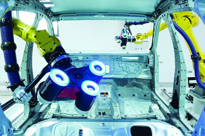
Hexagon’s Cognitens WLS400A white-light scanning system is available from Exact Metrology. Image courtesy of Exact Metrology.
A Light Touch
The electronic touch trigger probe was developed in the early 1970s and is still hard to beat for accuracy. Renishaw Inc., West Dundee, Ill., which was co-founded by the touch probe’s inventor, offers probes that are repeatable to 0.25µm.
Where optical scanning has tactile probes beat is in speed. It’s the difference between physically moving a pencil point vs. a spotlight beam around a tabletop. The latest generation of white-light scanners can obtain data that contains more than 8 million points in an area as small as 30mm2 in only a few seconds.
“If you are inspecting a part that has a lot of intricate shapes or intricate surfaces, you may prefer a laser scanner or white-light scanner in order to pick up those features. It would take too long with a touch probe,” said Ron Hicks, vice president of services at Automated Precision Inc. (API), Newport News, Va. “The customer may have a requirement that you measure something to, say, a thousandth of an inch, and you can’t quite do that with your laser scanner. But you might be able to do it with a tactile probing device mounted on an articulated arm.”
Red or White?
Scanners, whether laser-based (usually red) or white-light-projection-based, capture more data in an instant than the single point of a touch probe. Both the laser scanner and the white-light scanner are used at close range to quickly record data to a submillimeter level of accuracy. One difference between the two scanning methods is that a laser system picks up the data in a single sweep of its red beam. A white-light system, by design, depends on multiple shots of the same area to make calculations.
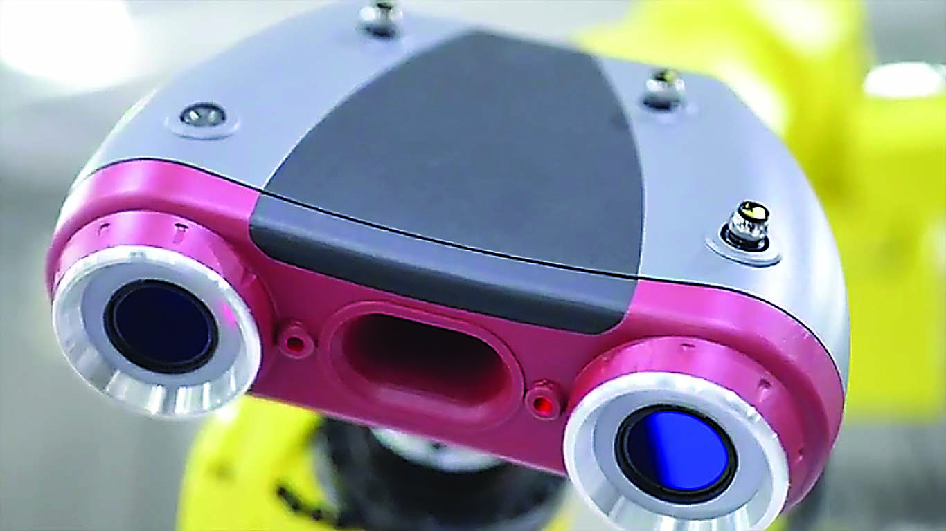
API’s RapidScan 3D scanning system uses infrared instead of white light. Image courtesy of API.
Hicks compared using a white-light scanner to taking photos of a part. “You may need to take multiple ‘shots,’ scanning at different angles, in order to capture all the information you need.” But because the user captures a lot of data that may not be needed, he added, it may slow the process.
In contrast, for many inspection tasks “you can swipe the part a couple of times with a laser scanner and pick up everything you need—without a lot of excess data to contend with,” Hicks said. “You have more discretion as to what you would really like to measure.”
Over time, Hicks has found that a laser scanner is the right tool for inspecting many parts. Inspection is different than prototyping or reverse engineering. “You’re really just trying to understand if it’s built correctly. You don’t need all that extra data,” he said.
Another advantage of a laser scanner, according to Dean Solberg, co-president of Exact Metrology, Brookfield, Wis., is that, typically, it can scan deeper into pockets than white-light scanners can. “If I have a 2"-dia. hole that’s 2" deep, I can get all the way to the bottom of that hole with a laser scanner, as well as scan the walls and so forth. The scanning time will be faster using a laser than with structured light.” (Solberg prefers the term “structured-light scanning” over “white-light scanning,” because many newer white-light systems actually use blue or another color of light to minimize the interference that ambient light can cause.)
“Scanning the bottom of that 2" hole with a structured-light scanner is going to take a whole lot of gyrations, and you may not be able to reach the bottom,” Solberg said. The reason is both cameras of the typical structured-light system have to be able to see the bottom of the hole to gather reliable data.
“Most likely you aren’t going to be able to do that with standard structured-light systems,” he said.
Combining Touch and Scan
Laser scanners are commonly positioned by mounting them on an articulated arm, which makes them easy to pair with other kinds of arm-mounted measuring systems.
API’s Hicks explained that an accurate method would be to have a portable CMM with a touch probe on an articulated arm. Depending on the accuracy requirements, Hicks said, “you may opt to use the point probe and then augment it with a laser scanner—basically have multiple input methods for the same part.” Everything would be in the same coordinate system.
Solberg elaborated. “With a portable arm, I have the ability to switch between probing and scanning.” As an example, he pointed to a foundry application with a pattern he wanted to scan. The alignment system he gathered was both more repeatable and accurate because he started with the probing system. The touch-probe system is “extremely flexible, always a little bit more accurate than using the scanner alone,” Solberg continued. “The ability to switch from a scanner to a probe and back again gives you the higher accuracy and repeatability of the probe along with the scanner’s advantages.”
Combining multiple measurement methods in a single system—call it the Swiss Army knife approach—is being provided by numerous measurement equipment makers. One of the most recent examples is the 300GMSL multiple-sensor gear inspection system from Gleason Corp., Rochester, N.Y. This system adds laser scanning to a platform that already included tactile probing, surface finish measurement and Barkhausen Noise Analysis to detect grinding burn.
The system, unveiled in May, provides tactile-probing methods for inspecting conventional gear data on spur and helical cylindrical gears, as well as straight, spiral and hypoid bevel gears with diameters up to 300mm (11.81"). Noncontact laser-sensor scanning of tooth flanks is provided to support gear development.
“Complete topography data can be recorded far more rapidly than with conventional tactile probing, with comparable results,” said Christian Albrecht, Gleason’s director of global marketing.
Albrecht explained that the integration of laser scanning and associated 3D graphics with a CAD interface considerably expands the functionality and the range of applications for this machine platform. He added that the system can be used for rapid measurement of topography in regular production operations and to satisfy the increasingly stringent requirements of gear inspection. “Compliant, soft materials—such as plastic gears—can be inspected without sustaining damage.”
Structural Improvements
Laser scanners have traditionally had some advantages over white-light scanning, including lower cost, better accuracy and no interference from ambient light. But these advantages are lessening.
“The cost of structured-light systems has come down appreciably,” Solberg said. “There’s a lot of low-end, $15,000-to-$30,000 systems out there that are technologically able to handle specific niches,” as well as the more versatile general-purpose systems.
In the past, Hicks would have no hesitation saying that laser scanners offered better accuracy than white-light scanners. Now he is more circumspect. “Some of the white-light systems are claiming very good accuracy,” Hicks said. “Usually, you’re looking at accuracies of about 40µm to 50µm with a white-light scanner, and you can usually get better than that with a laser scanner. But new white-light systems coming out reportedly can match the laser scanner’s accuracy.”
The issue of ambient light interfering with white-light scanning remains an issue. Hicks described measurement sessions using the white-light scanner when, because of the ambient lighting and the color of the part being measured, he and his colleagues had to play around with the lighting and the focus of the scanner to develop an adequate scan of the object. The white-light scanner “is a more delicate instrument, in terms of getting the right exposure,” he said. With the laser scanner, “as long as you can get a reading, you’re usually off to the races.”
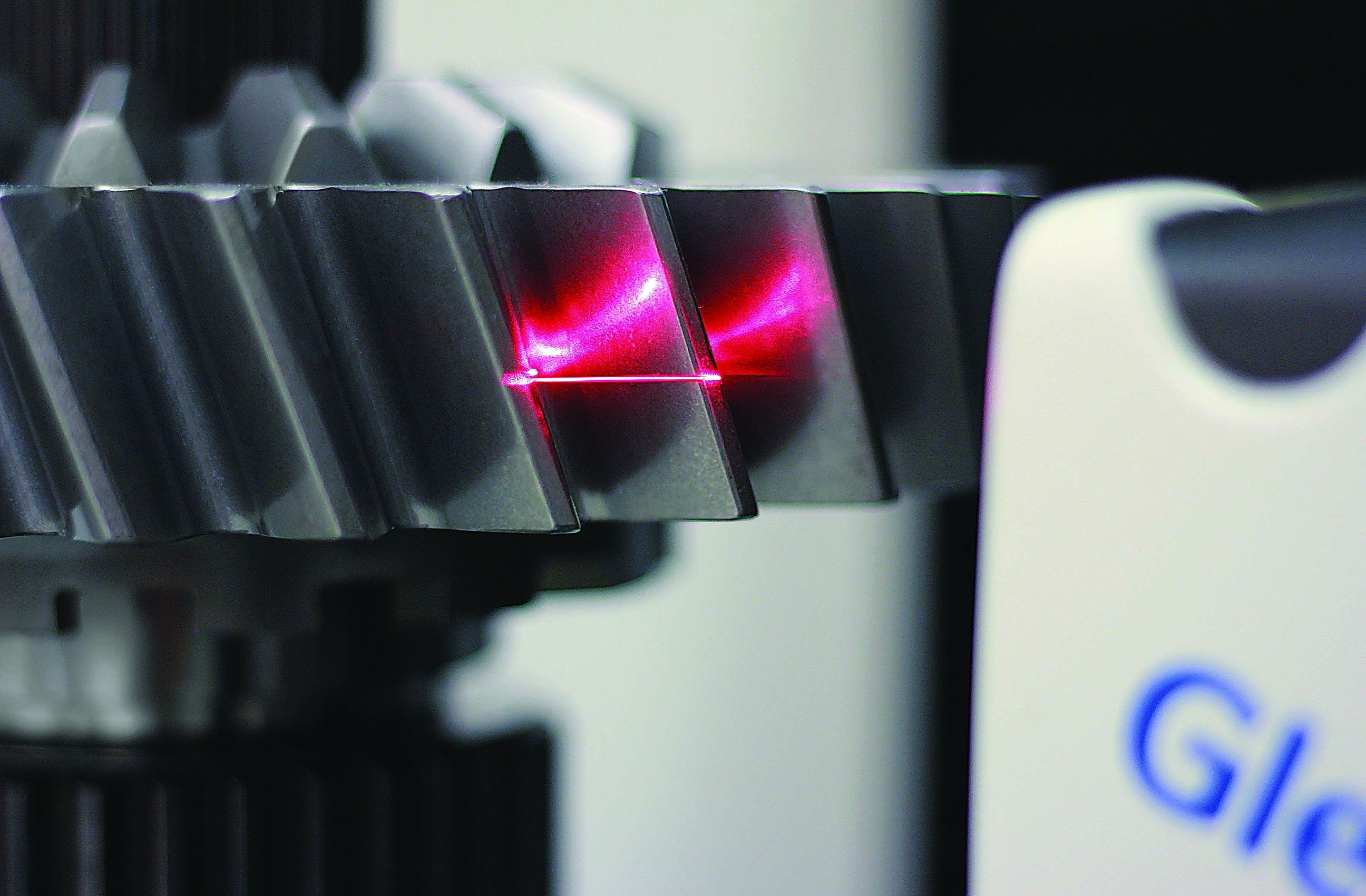
Gleason’s 300GMSL gear inspection system integrates laser scanning with other measuring systems. Image courtesy of Gleason.
Solberg noted the ambient light issue is being addressed by eschewing white light for specific frequencies, such as blue or green. “There’s a big push out there right now for blue-light scanning over white-light scanning,” he said. “However, we haven’t seen appreciable differences between the blue-light and the white-light scanners.”
Meanwhile, the product development side of Hicks’s company, API, has added another frequency to the mix. The API RapidScan system features an infrared projector and cameras instead of white or blue light.
Race to Automation
Automation continues to be a trend in U.S. manufacturing. This trend, so far, has favored white-light scanning over laser scanning. “Where they’re going with these (white)-light scanners is automation,” Solberg said. “For example, you can use it to look for dimensional defects on the side of a car—automating tasks in a way that hasn’t been done yet with an articulated-arm-based scanning system.”
Hicks agreed. “With a white-light scanner on a robot, you could automate simple inspection processes. You can use it to measure a lot of parts to a high degree of accuracy in a short period of time.”
Hicks, Solberg and Gleason’s Albrecht all believe there will be a place going forward for both laser scanning and white-light scanning, as well as tactile systems, photogrammetry and newer approaches such as CT scanning.
“Each tool is meant for a specific application—like using the right tool in the toolbox,” Solberg said. “You don’t use a hammer when you need a screwdriver.”
Contact Details
Contact Details
Contact Details
Related Glossary Terms
- computer-aided design ( CAD)
computer-aided design ( CAD)
Product-design functions performed with the help of computers and special software.
- grinding
grinding
Machining operation in which material is removed from the workpiece by a powered abrasive wheel, stone, belt, paste, sheet, compound, slurry, etc. Takes various forms: surface grinding (creates flat and/or squared surfaces); cylindrical grinding (for external cylindrical and tapered shapes, fillets, undercuts, etc.); centerless grinding; chamfering; thread and form grinding; tool and cutter grinding; offhand grinding; lapping and polishing (grinding with extremely fine grits to create ultrasmooth surfaces); honing; and disc grinding.
- metrology
metrology
Science of measurement; the principles on which precision machining, quality control and inspection are based. See precision machining, measurement.
- tolerance
tolerance
Minimum and maximum amount a workpiece dimension is allowed to vary from a set standard and still be acceptable.
Author

Michael Anderson, former senior editor at Cutting Tool Engineering magazine, holds a master's degree in written communication from Eastern Michigan University. He has been professionally writing about manufacturing technology since 1998, including more than 10 years at the Society of Manufacturing Engineers.
Contributors
Automated Precision Inc.
(800) 537-2720
www.apisensor.com
Exact Metrology
(866) 722-2600
www.exactmetrology.com
Gleason Corp.
(585) 473-1000
www.gleason.com