Software evolves with industry

Author Stas Mylek
Published
June 02, 2020 - 09:00am

The challenges of high-temperature materials like titanium, plus increased pressure to reduce cycle times and costs, are forcing manufacturers in aerospace, energy, medical and other industries to seek new methods to machine these materials in the most productive ways possible.

CAM software providers continually improve their products to keep pace with the evolution of materials while adapting to innovations on the side of cutting and machine tools. The goal is to develop toolpath strategies that address the machining characteristics and challenges that these materials present, as well as to exploit developments with machine and cutting tools. Research and testing often uncover surprises.

For example, Tolland, Connecticut-based CNC Software Inc., developer of Mastercam, operates a manufacturing lab for toolpath and machining research to gain hands-on feedback on CAM developments. Personnel ranging from application engineers and product specialists to the partnership team use the lab to test new ideas under typical shop conditions. What makes the lab unique is its collaboration with industry leaders in the machine and cutting tool fields. The facility regularly cycles through equipment to accurately replicate customer environments, and cutting tool partners often use the lab to test their most recent technological advancements.


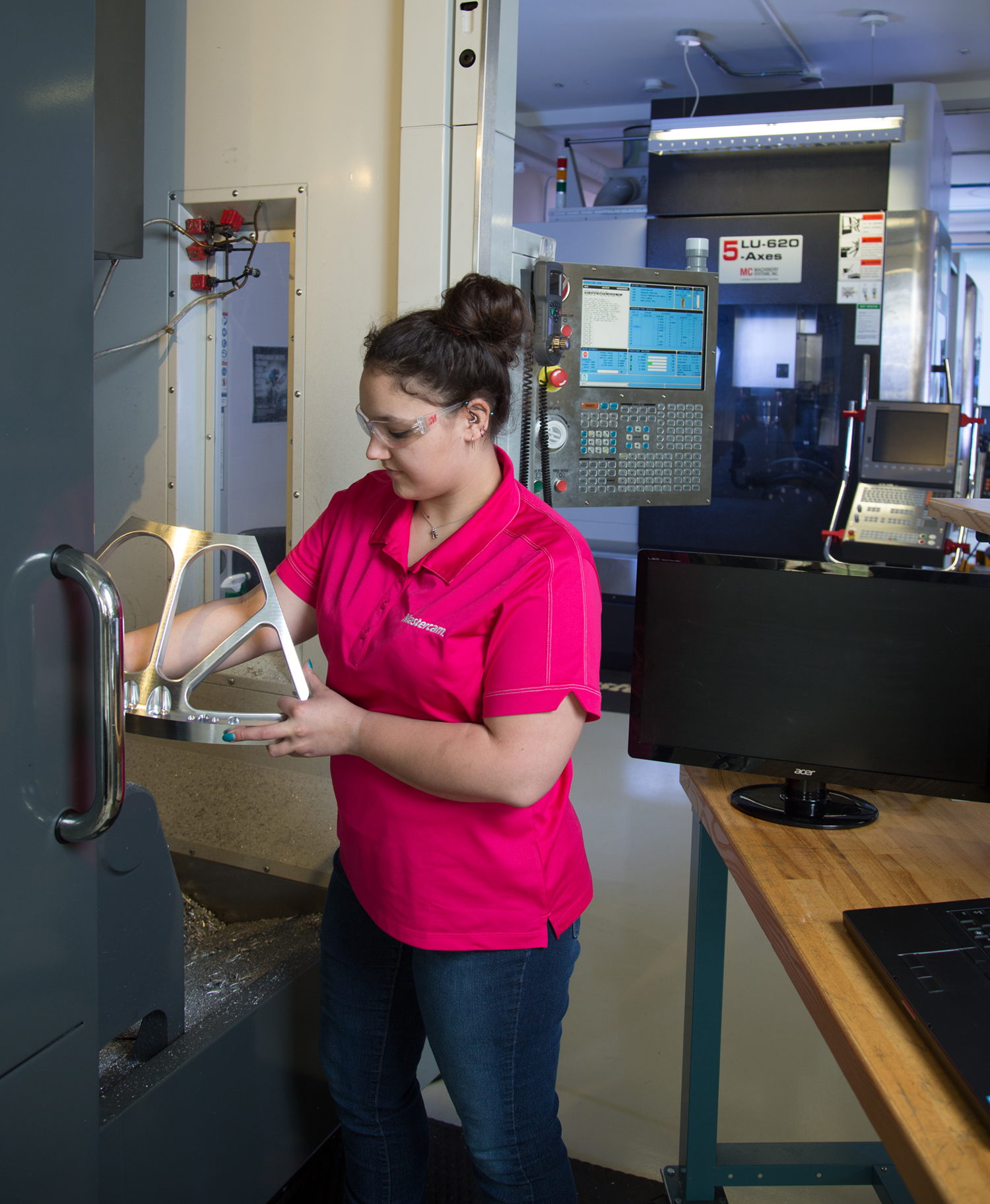
CNC Software operates a manufacturing lab for toolpath and machining research to gain hands-on feedback on CAM developments. Image courtesy of CNC Software

A recent project involved testing a counterintuitive roughing strategy that potentially could translate into large cycle time reductions for titanium parts. This theory was grounded in earlier lab tests. Leveraging the optimum cutting condition and constant chip load capabilities of Mastercam’s Dynamic Motion toolpaths, the lab ran a test with D2 tool steel at an 80% step-over and 200% DOC with a 9.525 mm (0.375") dia. tool. Even at a more traditional feed rate of 1.7 m/min. (65 ipm), the material removal rate was still over 40% greater than using the high-speed machining, radial chip thinning approach that’s more common in the industry. This new “power cutting” method required higher horsepower usage and more rigid workholding, yet the MRR and cycle times were far better. The lab wondered if similar results were possible in superalloys, such as titanium.

The lab often is approached by cutting tool partners to test new tools, and the team’s effort isn’t limited to our own shop. So when Arlington, Texas-based Iscar Metals Inc. offered to test a new tool at the company’s new technology center in Charlotte, North Carolina, on an Okuma MB-4000 horizontal machining center, we jumped at the chance.

Tom Raun, chief technical officer at Iscar Metals, suggested using a 9.525 mm ECKI (Ti-Turbo) series carbide endmill for the titanium test cut. This line of endmills is designed specifically for aggressive rough milling of titanium and is capable of full slot machining at depths up to two times the cutting diameter. The HMC had the horsepower and performance needed to compare a high-speed chip thinning approach with a power cutting strategy to validate any cycle time gains.

Using Dynamic Motion, the first test cuts used typical HSM parameters: a 15% step-over at a depth of 19.05 mm (0.75") and a feed rate of 1.07 m/min. (42 ipm). A second run machined the part at an 80% step-over and the same 200% DOC but at a typical feed rate of 229 mm/min. (9 ipm). Initial results were promising but not jaw-dropping. The average difference between making fast, multiple passes and performing a large step-over with fewer passes at a slower feed rate was only about a 4% improvement in cycle time. It was time to return to the drawing board.


With most HSM applications, climb cuts are the norm, yet they can create extra motion as a cutter rapids back for the next pass (left). However, to address some material applications, a bidirectional option was added to Mastercam’s Dynamic Milling toolpaths, resulting in an average cycle time reduction of 15% (right). Image courtesy of CNC Software

With most HSM applications, climb cuts are the norm, yet they can create extra motion as a cutter rapids back for the next pass. However, to address some material applications, a bidirectional option was added to Dynamic Motion. This allowed alternating passes of climb cutting and conventional with small exit and entry loops between each pass. At nearly full slot engagement, a conventional cutting mode could work because the cutting edge would quickly enter material and avoid any burnishing. Alternating cut motion then would eliminate extra travel and cycle time. The only question was how it would work in titanium.

Testing was the eye-opener. The bidirectional option greatly reduced extra motion and kept the tool in the cut longer. At a more traditional feed rate and with the same cut parameters, the cut was flawless. Yet the real telltale clue was the sound. The cut sounded no different in the conventional pass than it did in the climb cut. Entries and exits with material were tight and kept travel to an absolute minimum. But cycle time reduction was the real highlight.

On our 203 mm × 203 mm (8"×8") workpiece, overall cycle time dropped by 15%. Extrapolated across larger parts with more elongated machining areas characteristic of aerospace components, this innovative strategy, combined with the right tooling and machine, could save as much as 30% to 45% of total machining time.

Lab testing and outside-the-box thinking are uncovering novel approaches to difficult machining challenges. Collaboration among leading metalworking industry suppliers makes this an exciting time to help shape the future of global manufacturing.    


Related Glossary Terms

  • burnishing

    burnishing

    Finishing method by means of compressing or cold-working the workpiece surface with carbide rollers called burnishing rolls or burnishers.

  • computer numerical control ( CNC)

    computer numerical control ( CNC)

    Microprocessor-based controller dedicated to a machine tool that permits the creation or modification of parts. Programmed numerical control activates the machine’s servos and spindle drives and controls the various machining operations. See DNC, direct numerical control; NC, numerical control.

  • computer-aided manufacturing ( CAM)

    computer-aided manufacturing ( CAM)

    Use of computers to control machining and manufacturing processes.

  • endmill

    endmill

    Milling cutter held by its shank that cuts on its periphery and, if so configured, on its free end. Takes a variety of shapes (single- and double-end, roughing, ballnose and cup-end) and sizes (stub, medium, long and extra-long). Also comes with differing numbers of flutes.

  • feed

    feed

    Rate of change of position of the tool as a whole, relative to the workpiece while cutting.

  • gang cutting ( milling)

    gang cutting ( milling)

    Machining with several cutters mounted on a single arbor, generally for simultaneous cutting.

  • machining center

    machining center

    CNC machine tool capable of drilling, reaming, tapping, milling and boring. Normally comes with an automatic toolchanger. See automatic toolchanger.

  • metalworking

    metalworking

    Any manufacturing process in which metal is processed or machined such that the workpiece is given a new shape. Broadly defined, the term includes processes such as design and layout, heat-treating, material handling and inspection.

  • milling

    milling

    Machining operation in which metal or other material is removed by applying power to a rotating cutter. In vertical milling, the cutting tool is mounted vertically on the spindle. In horizontal milling, the cutting tool is mounted horizontally, either directly on the spindle or on an arbor. Horizontal milling is further broken down into conventional milling, where the cutter rotates opposite the direction of feed, or “up” into the workpiece; and climb milling, where the cutter rotates in the direction of feed, or “down” into the workpiece. Milling operations include plane or surface milling, endmilling, facemilling, angle milling, form milling and profiling.

  • step-over

    step-over

    Distance between the passes of the toolpath; the path spacing. The distance the tool will move horizontally when making the next pass. Too great of a step-over will cause difficulty machining because there will be too much pressure on the tool as it is trying to cut with too much of its surface area.

  • superalloys

    superalloys

    Tough, difficult-to-machine alloys; includes Hastelloy, Inconel and Monel. Many are nickel-base metals.

  • toolpath( cutter path)

    toolpath( cutter path)

    2-D or 3-D path generated by program code or a CAM system and followed by tool when machining a part.

Author

Applications Adviser, CNC Software Inc.
800-228-2877

Stas Mylek is applications adviser for CNC Software Inc., Tolland, Conn. For more information about the company’s Mastercam CAD/CAM software, call (800) 228-2877 or visit www.mastercam.com.