Saving time saves money when machining parts. When producing a run of 18 prototype parts with variations, Concept Reality Inc. even saved enough time to pay for a performance package for its CAM software, said Chris Nunn, president of the Vancouver, Wash., aerospace contract manufacturer. “They don’t give that away.”
“That” is the hyperMILL MAXX Machining finishing module for the hyperMILL CAM software suite from Open Mind Technologies USA Inc., Needham, Mass. According to the software developer, the finishing module efficiently uses machine tool and cutting tool options in relation to part surface quality and cutting speed. The module succeeds by applying a 5-axis tangent plane machining strategy and conical barrel cutters, where the software and conical barrel cutters combined to enable a more successful, highly efficient 5-axis machining strategy.
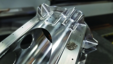
The hyperMILL MAXX Machining finishing module enables taking large step-overs with toolpaths
for conical barrel cutters when finishing this aerospace part. Image courtesy of Concept Reality
Geometrically, a barrel cutter has a large cutting radius on its side, enabling the tool to access much more surface area of a part, allowing a large step-over between passes, stated Alan Levine, managing director of Open Mind Technologies. The conical barrel cutter follows the general design of barrel cutters, with a small arc segment of a large radius on its profile. However, the adaptation positions the arc segment at an angle to the axis of the cutter. This position opens the conical barrel cutter to a broader set of applications while delivering the same benefits.
A conical barrel cutter can make step-overs up to 8mm, according to Open Mind. An end user does not need to switch cutters to finish adjacent areas, such as rounded interior corners.
“The alternative is using a ballnose tool. It’s not as efficient, and you have to hang the tool out further,” Nunn said in comparison with a conical barrel cutter. A conical barrel cutter, on the other hand, enables a more rigid setup. “This way, you could choke up on it more.”
The finishing module is suitable for planar, ruled and arched surfaces often found in complex aerospace components produced via 5-axis machining. Open Mind also offers high-performance modules for roughing and drilling.
“The hyperMILL MAXX Machining finishing process allowed us to increase our step-down between toolpaths by 12 times when compared with traditional machining methods using ballnose cutting tools,” Nunn said. “This saved us 5 hours per part in finishing operations while reducing the cusp height.”
A cutting tool must step over and make numerous adjacent cuts to fully machine a part feature. As a result, a small cusp of material, or scallop, will remain between the cuts. “There is an amount of material that is in error,” Nunn said.
Because of the large step-overs a conical barrel cutter takes, the total toolpath length for a surface is far less than with ballnose endmills, Levine noted.
Nunn learned about the finishing module from a YouTube video that showed an aerospace structural part being machined on a Grob G550 machine. “It is more widely used in Europe,” he said about the module, “but U.S. manufacturers are starting to catch on.”
Concept Reality applied two or three different size Emuge conical barrel cutters when finishing the prototypes, Nunn said.
Using the finishing module does require extra programming time, Nunn said. However, being able to reduce cycle times more than 90 percent, depending on the application, provides more than adequate compensation.
Related Glossary Terms
- computer-aided manufacturing ( CAM)
computer-aided manufacturing ( CAM)
Use of computers to control machining and manufacturing processes.
- cutting speed
cutting speed
Tangential velocity on the surface of the tool or workpiece at the cutting interface. The formula for cutting speed (sfm) is tool diameter 5 0.26 5 spindle speed (rpm). The formula for feed per tooth (fpt) is table feed (ipm)/number of flutes/spindle speed (rpm). The formula for spindle speed (rpm) is cutting speed (sfm) 5 3.82/tool diameter. The formula for table feed (ipm) is feed per tooth (ftp) 5 number of tool flutes 5 spindle speed (rpm).
- step-over
step-over
Distance between the passes of the toolpath; the path spacing. The distance the tool will move horizontally when making the next pass. Too great of a step-over will cause difficulty machining because there will be too much pressure on the tool as it is trying to cut with too much of its surface area.
- toolpath( cutter path)
toolpath( cutter path)
2-D or 3-D path generated by program code or a CAM system and followed by tool when machining a part.
END USER: Concept Reality Inc., (360) 695-3860, www.conceptreality.com
SOLUTION PROVIDER: Open Mind Technologies USA Inc., (888) 516-1232, www.openmind-tech.com
CHALLENGE: educe the finishing time when producing a run of prototype parts.
SOLUTION: A finishing module for CAM software.