Using computers to simulate and analyze the metalcutting process helps tool manufacturers improve machining and predict how well a product will perform in the real world. Some of the factors considered during these simulations are horsepower consumption, chipbreaking efficiency, chip evacuation, and tool life.
Ingersoll Cutting Tool Co., Rockford, IL, is one of the companies working to simulate the metalcutting process on computers. The company’s aim is to optimize tool design and machining methods in a closed-loop, iterative environment before a tool is actually manufactured. This has resulted in better performing products being brought to market faster.
Ingersoll has developed models for turning, milling, and drilling. Cutting parameters that can be predicted include stress, strain, strain rate, deformed-chip thickness, and chip-curl radius. They can be obtained for a given tool/workpiece combination at various speeds and feed rates.
Machining models that incorporate FEA are generally based on 2-D orthogonal cutting. Ingersoll’s model simulates the metalcutting process in three dimensions.
Developing 3-D Capability
Earlier research into the mechanics of machining focused on shear-zone models. These models ignored some of the significant features of metalcutting, such as frictional conditions on the tool-rake face, workhardening, and the effect of extreme temperatures on workpiece materials.
During the last two decades, researchers have successfully applied finite element analysis (FEA) to the metalcutting process. FEA is able to handle complex material-property definitions, tool/chip interactions, and non-linear geometric boundaries, such as the surface of the chip. FEA can also predict local variables, like stress and temperature distribution.
In order to simplify the computations involved, machining models that incorporate FEA are generally based on 2-D orthogonal cutting. Few models have been developed that simulate 3-D machining. And the ones that have are greatly simplified, which casts doubt on the reliability of their predictions. The accuracy of any FEA model is directly dependent on the number of assumptions made, as well as the effort involved in correlating the computer model and the real application.
To be a truly effective predictive tool, a machining simulator should be sensitive to changes in material properties, operating conditions, cutting parameters, and tool geometry. One of the hurdles in developing such a simulator is that the mechanics of the machining operation are largely unknown. Also, there is a lack of process data for the area of interest near the tool tip. Coupled with this is a need for an efficient software code—one that can handle large deformations and complex contact conditions simultaneously, so that computer run times are practical. The conditions that the program’s calculations must take into account include sticking and sliding friction, as well as the loss or gain of contact that occurs at the tool/chip interface as the chip develops.
Ingersoll’s Simulator
Ingersoll has developed a machining simulator by customizing ABAQUS, a general-purpose, FEA software package. The company’s proprietary FEA code receives input about tool and workpiece geometries from Pro/ENGINEER software. Other inputs are material properties, contact conditions, boundary conditions, and thermal properties. Output data include cutting forces and the temperatures that develop in the tool and the workpiece.
Currently, the simulator takes into account material properties at high cutting speeds and feed rates. The simulator also incorporates a failure model that is designed to allow the stable removal of material (elements) from a finite element mesh if the workpiece tears or rips. Deletion of elements facilitates separating the chip from the workpiece.
For any predictive computer model to simulate real-world machining conditions, material properties must be accurately represented. Material properties, such as flow stress, are unique for each material and are dependent upon the temperatures and velocities encountered at the tool tip. The material properties of metals at high velocities and temperatures cannot be obtained easily with conventional methods of physical testing. As a result, predicted values of cutting forces and temperatures do not correspond to values obtained in actual cutting operations. A realistic and dependable simulation of the process must incorporate the material’s behavior at the specified process conditions.
Ingersoll’s machining simulator uses experimental data in combination with FEA simulations to provide data about the behavior of materials. Forces on the tool are directly correlated to the deformation energy during the cut. During the developmental stages of the project, comparisons of simulated and actual cutting forces were conducted. A Kistler dynamometer was used to test various workpiece materials at several cutting parameters.
Friction at the tool/chip interface plays an important role in determining chip formation and the forces and temperatures developed in this region. FEA can model the interaction between chip and tool to an extent. The Ingersoll simulator is able to differentiate the effects of various friction factors on chip formation, as well as other process parameters.
Simulator in Action
A drill insert that Ingersoll recently developed serves as an example of the simulator’s effectiveness in optimizing tool design.
Shops that drill soft steels (<220 Bhn) have tremendous difficulty breaking chips that are of a manageable size. Chips tend to be stringy, even if the operator uses the correct machining parameters and the best inserts available on the market (Figure 1). Unbroken chips are difficult to evacuate through the gullets. They cause hole-size problems, clog chip-conveyor systems, and pose safety risks when ejected from the tool. Further compounding the problem is the fact that the hardnesses of the raw materials a shop receives tend to vary from lot to lot.

Figure 1: Ingersoll used its simulator to help develop an insert for drilling soft steels. Chips cut from these materials tend to be stringy and difficult to break.
Ingersoll established three criteria that the new insert had to meet:
- operate at an acceptable surface speed and feed rate;
- work across a range of material hardnesses and compositions; and
- produce small, curled, manageable chips.
The simulator’s flexibility allowed a matrix of design features to be evaluated for effectiveness and optimal performance, both independently and in combination. Varying any one feature independently altered the behavior of chipflow considerably. The final design incorporated several chipbreaking schemes that had been tested.
Output from the evaluation produced a typical chip, as seen in Figure 2. Physical testing substantiated the computer models. The new insert produced the chips shown in Figure 3.
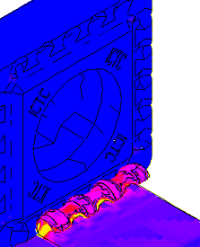
Figure 2: Simulated chip formation with insert designed for soft steels.
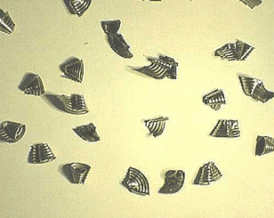
Figure 3: Ingersoll developed its new drill insert based on data collected during simulations. Shown are actual C-shaped chips cut by the insert.
Performance tests showed that the final design had the broadest range of chipbreaking abilities ever achieved by a single insert design when drilling soft materials. This case proved to be an “out of the box” success, meaning only one prototype mold had to be constructed.
Conclusions
The use of dynamic FEA adds a scientific component to the metalcutting process. Clearly, it forms the leading edge for the design and development of advanced cutting tools. Beyond tool optimization, it greatly reduces development costs and the time needed to bring a new product to market.
In Ingersoll’s opinion, the use of FEA to simulate the metalcutting process is a great breakthrough for the industry. And although fairly new with respect to optimizing tool designs, use of it is expected to grow rapidly.
Off-the-Shelf Modeling Software for Metalcutting
Several universities and companies are developing proprietary software programs that model the machining process. A software package from Third Wave Systems Inc. is reportedly the first commercially available, experimentally validated modeling program dedicated to the metalcutting process.
“Unlike general-purpose simulation software,” says Third Wave’s sales and marketing manager, Paul Bayer, “AdvantEdge™ was built from the ground up to model the cutting process.”
Third Wave introduced Version 3.0 of the software in mid-1997. The Minneapolis-based company released Version 3.1 in February 1999. In addition to the capabilities of the earlier program, Version 3.1 allows the user to model the cutting process with coated tools.
AdvantEdge software employs advanced material-modeling techniques and adaptive finite elements to capture the microsecond-by-microsecond changes that occur at the tool tip and to the chip and workpiece. It can be used to model turning, up and down milling, sawing, and broaching. Workpiece materials that can be modeled include assorted grades of aluminum and steel, copper, Inconel, and 316 stainless steel. Among the tool materials and coatings that can be simulated are carbides, ceramics, ultrahard materials, cobalt-base alloys, HSS, TiN, TiCN, and Al2O3.
Bayer says that AdvantEdge software lets companies accurately predict the effects of cutting on the tool’s edge and geometry at user-defined process parameters. “It really saves time,” he says. “Someone can evaluate different geometries, for example, without having to run out to the machine to test them.”
– Don Nelson
1

2

3

4
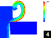
This sequence demonstrates AdvantEdge software simulating chip formation during a turning operation on 4340 steel. Process conditions include an insert with a near-0° rake angle, a 0.500mm/rev. feed rate, and a 900m/min. speed. 1: The chip begins to form. Two segments are visible, as is the strain induced in the segments (depicted by the colored contours). 2: The fully developed chip begins to curl back upon itself and contact the workpiece. The outer edge of the chip exhibits very high strain, typical of curl. 3 & 4: The curl of the chip is now influenced by its contact with the workpiece, and it begins to skid and slide along the workpiece, changing its effective radius. This also creates localized areas of high strain at the back of the chip.
About the Authors
Sumanth Kumar is a development engineer and Brian Hoefler is manager of materials technology at Ingersoll Cutting Tool Co., Rockford, IL.
Related Glossary Terms
- 2-D
2-D
Way of displaying real-world objects on a flat surface, showing only height and width. This system uses only the X and Y axes.
- 3-D
3-D
Way of displaying real-world objects in a natural way by showing depth, height and width. This system uses the X, Y and Z axes.
- alloys
alloys
Substances having metallic properties and being composed of two or more chemical elements of which at least one is a metal.
- broaching
broaching
Operation in which a cutter progressively enlarges a slot or hole or shapes a workpiece exterior. Low teeth start the cut, intermediate teeth remove the majority of the material and high teeth finish the task. Broaching can be a one-step operation, as opposed to milling and slotting, which require repeated passes. Typically, however, broaching also involves multiple passes.
- ceramics
ceramics
Cutting tool materials based on aluminum oxide and silicon nitride. Ceramic tools can withstand higher cutting speeds than cemented carbide tools when machining hardened steels, cast irons and high-temperature alloys.
- climb milling ( down milling)
climb milling ( down milling)
Rotation of a milling tool in the same direction as the feed at the point of contact. Chips are cut to maximum thickness at the initial engagement of the cutter’s teeth with the workpiece and decrease in thickness at the end of engagement. See conventional milling.
- coated tools
coated tools
Carbide and high-speed-steel tools coated with thin layers of aluminum oxide, titanium carbide, titanium nitride, hafnium nitride or other compounds. Coating improves a tool’s resistance to wear, allows higher machining speeds and imparts better finishes. See CVD, chemical vapor deposition; PVD, physical vapor deposition.
- dynamometer
dynamometer
When drilling, a device for measuring the generated torque and axial force (thrust). When milling, a device for measuring the generated torque and feed force. When turning, a device for measuring the tangential, feed and radial forces.
- feed
feed
Rate of change of position of the tool as a whole, relative to the workpiece while cutting.
- flow stress
flow stress
Uniaxial true stress at the onset of plastic deformation in a metal.
- gang cutting ( milling)
gang cutting ( milling)
Machining with several cutters mounted on a single arbor, generally for simultaneous cutting.
- high-speed steels ( HSS)
high-speed steels ( HSS)
Available in two major types: tungsten high-speed steels (designated by letter T having tungsten as the principal alloying element) and molybdenum high-speed steels (designated by letter M having molybdenum as the principal alloying element). The type T high-speed steels containing cobalt have higher wear resistance and greater red (hot) hardness, withstanding cutting temperature up to 1,100º F (590º C). The type T steels are used to fabricate metalcutting tools (milling cutters, drills, reamers and taps), woodworking tools, various types of punches and dies, ball and roller bearings. The type M steels are used for cutting tools and various types of dies.
- metalcutting ( material cutting)
metalcutting ( material cutting)
Any machining process used to part metal or other material or give a workpiece a new configuration. Conventionally applies to machining operations in which a cutting tool mechanically removes material in the form of chips; applies to any process in which metal or material is removed to create new shapes. See metalforming.
- milling
milling
Machining operation in which metal or other material is removed by applying power to a rotating cutter. In vertical milling, the cutting tool is mounted vertically on the spindle. In horizontal milling, the cutting tool is mounted horizontally, either directly on the spindle or on an arbor. Horizontal milling is further broken down into conventional milling, where the cutter rotates opposite the direction of feed, or “up” into the workpiece; and climb milling, where the cutter rotates in the direction of feed, or “down” into the workpiece. Milling operations include plane or surface milling, endmilling, facemilling, angle milling, form milling and profiling.
- rake
rake
Angle of inclination between the face of the cutting tool and the workpiece. If the face of the tool lies in a plane through the axis of the workpiece, the tool is said to have a neutral, or zero, rake. If the inclination of the tool face makes the cutting edge more acute than when the rake angle is zero, the rake is positive. If the inclination of the tool face makes the cutting edge less acute or more blunt than when the rake angle is zero, the rake is negative.
- sawing
sawing
Machining operation in which a powered machine, usually equipped with a blade having milled or ground teeth, is used to part material (cutoff) or give it a new shape (contour bandsawing, band machining). Four basic types of sawing operations are: hacksawing (power or manual operation in which the blade moves back and forth through the work, cutting on one of the strokes); cold or circular sawing (a rotating, circular, toothed blade parts the material much as a workshop table saw or radial-arm saw cuts wood); bandsawing (a flexible, toothed blade rides on wheels under tension and is guided through the work); and abrasive sawing (abrasive points attached to a fiber or metal backing part stock, could be considered a grinding operation).
- titanium carbonitride ( TiCN)
titanium carbonitride ( TiCN)
Often used as a tool coating. See coated tools.
- titanium nitride ( TiN)
titanium nitride ( TiN)
Added to titanium-carbide tooling to permit machining of hard metals at high speeds. Also used as a tool coating. See coated tools.
- turning
turning
Workpiece is held in a chuck, mounted on a face plate or secured between centers and rotated while a cutting tool, normally a single-point tool, is fed into it along its periphery or across its end or face. Takes the form of straight turning (cutting along the periphery of the workpiece); taper turning (creating a taper); step turning (turning different-size diameters on the same work); chamfering (beveling an edge or shoulder); facing (cutting on an end); turning threads (usually external but can be internal); roughing (high-volume metal removal); and finishing (final light cuts). Performed on lathes, turning centers, chucking machines, automatic screw machines and similar machines.
- workhardening
workhardening
Tendency of all metals to become harder when they are machined or subjected to other stresses and strains. This trait is particularly pronounced in soft, low-carbon steel or alloys containing nickel and manganese—nonmagnetic stainless steel, high-manganese steel and the superalloys Inconel and Monel.