Instead of mechanical clamping devices to hold tools, this system relies on the thermal-expansion properties of the toolholders themselves.
More than one shop searching for the secret to higher productivity has found itself handicapped by its machining-center toolholders. Whether these shops hold their tools with collet chucks, with hydraulic chucks, or by some other mechanical method, they can’t reach the level of toolholding accuracy needed for high-speed, high-precision work. Their tools may be concentric, balanced, and rigid enough for lower speed machining, but when spindle speeds exceed 10,000 rpm, the forces acting on the tools magnify every imperfection.
From the standpoint of concentricity, rigidity, and balance, a machining-center tool machined in one piece—from the taper shank to the cutting edge—out of a solid block of HSS or carbide would be the ideal. There would be no junction between the tool and the toolholder to introduce instability into the setup, and the user would never have to worry about a toolholder clamping a tool off-center. However, the cost of stocking a toolcrib with these one-piece tools for a machining center would be astronomical.
There is one type of toolholder that seems to come close to the one-piece ideal without being prohibitively expensive. Rather than using a mechanical method to clamp the tool, this type of toolholder uses the concept of thermal expansion and contraction. A user heats the toolholder in a specially built, induction-heating unit (Figure 1). This causes the toolholder’s bore to expand enough for the user to insert a conventional tool. When the toolholder cools, its bore contracts around the tool, holding it with 10,000 lb. of force or more.
These shrink-fit systems require specially made toolholders, but they can use any standard tool, including solid-HSS or -carbide or insert-style, with straight or Weldon-flat shanks (Figure 2). Each toolholder is designed for a specific tool-shank diameter. The toolholders are available with any style of shank.
Solid Performance
Measurements of tools set in these shrink-fit toolholders show that the tool and toolholder together perform much like a one-piece tool would. The gripping force and concentricity with which tools are held in a shrink-fit toolholder allows users to increase speeds and feeds by 20% or more over the parameters they might use with other toolholders. A more precise set also reduces wear on the tool. Typically tool life increases 30% or more after a switch to shrink-fit toolholders.
The concentricity of shrink-fit tools is 0.0002" or better, and this accuracy is repeated with every tool change. To preset tools, the user simply controls the depth the shank extends into the bore; the contraction of the toolholder centers the tool automatically.
The shrink-fit toolholder and tool assembly resists centrifugal force as if the assembly were a one-piece tool. At high speeds, centrifugal force can cause the clamping mechanisms of other types of toolholders to expand and loosen their grip on the tool. But because it takes much greater force to expand solid metal, the centrifugal force generated by high-speed machining has little effect on the solid shrink-fit toolholder collar.
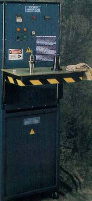
Figure 1: Toolholders are heated in a receptacle in the shelf of this induction-heating unit to expand them enough for the user to remove or insert tools.
The contraction of the toolholder rigidly locks the tool in place. A machine would have to drive the tool with more than 100 hp to turn the tool within the bore of the toolholder. The shrink-fit toolholder grips the tool with five times more force than toolholders using collets, set screws, or hydraulics do. The force the shrink-fit toolholder exerts on the tool is even greater than the force an average machine tool exerts on the retention knob holding the toolholder in the machine. This means that, in the presence of a great force, the toolholder would be pulled from the spindle before the tool would be shifted from its position in the toolholder.
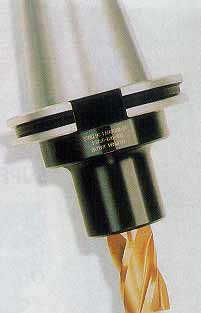
Figure 2: Shrink-fit toolholders can hold standard tools without any type of mechanical clamping system.
The shrink-fit toolholder’s ability to grip the entire tool shaft also contributes to the assembly’s rigidity. As the toolholder’s bore contracts around the tool shaft, force is applied equally around the tool’s circumference and along the entire length of the shaft inserted into the bore. Standard and hydraulic chucks typically cannot grip the tool shaft at the end of the bore. This leaves an area of the tool shank up to 1/4" wide where no force is applied.
For high-speed applications, a tool must be balanced as well as rigid and concentric. Imbalance, especially at high speeds, creates chatter, uneven chiploads, and poor finishes. It also puts a strain on the spindle bearings as the tool wobbles while it turns. The simplicity of the shrink-fit toolholder’s design contributes to its balance. There are no clamping mechanisms that must be counterbalanced. And with no set screws or moving parts to change position from tool change to tool change, shrink-fit toolholders with tools mounted in them remain in balance. Typically, the toolholders are dynamically balanced to G2.5 at 20,000 rpm. Special toolholders can be balanced to G1.0 at 40,000 rpm.
The shrink-fit toolholder design’s simplicity also helps keep the extension of the toolholder to a minimum. Because a shrink-fit toolholder does not require additional length to accommodate a clamping mechanism, it does not have to extend as far past the gage line as other types of toolholders do. The shorter extension further enhances the rigidity of a tool/toolholder assembly.

Figure 3: The induction coil encircling the toolholder's collar heats the toolholder to the proper temperature. An optional infrared sensor can be used to control the heating process.
Shrink-Fit Holders at Work
Shorter extensions were what Arden Engineering, Orange County, CA, was after when it switched to shrink-fit toolholders 10 years ago. As an aerospace manufacturer, Arden machines a range of materials having various hardnesses. A typical operation might employ a large milling cutter to rough out airframe parts on one of the shop’s Mazak or SNK machining centers.
Using conventional toolholders, Arden’s operators frequently had to contend with overhangs of 10" or more from the gage line to the tool tip. Such extreme lengths were necessary to provide room for tool-clamping devices in the toolholder’s collar. An additional area free of clamping mechanisms was necessary to allow automatic toolchangers to pick up and hold the toolholder. A typical CAT-50 toolholder, for example, required a 5" projection for the safety area and the toolholder mechanics combined. The overhangs compromised tool rigidity, and this led to chatter and increased tool wear, especially when milling titanium. In one application requiring a 1"-wide side cut 2" to 3" deep with a 2"-dia. endmill, the overhang made it impossible to obtain a good surface finish using conventional holders.
Arden solved its overhang problems by replacing 1,000 of its 6,000 CAT-50 toolholders with shrink-fit toolholders. Arden’s operators typically use the shrink-fit models to hold 2"-dia. M-42 HSS endmills. The change significantly reduced overhangs. In one application, a 10" overhang was reduced to 8".
According to Arden’s manufacturing manager, Danny Meisenbach, reducing overhangs has improved tool life and surface finishes. The tools in the shrink-fit toolholders stay sharpened four to five times longer than tools mounted in conventional holders do, he says. With the shrink-fit toolholders, even the application calling for a deep 1"-wide side cut with a 2"-dia. endmill can be performed satisfactorily.
Other shops that have used shrink-fit toolholders report similar increases in accuracy and throughput due to longer tool life and more aggressive machining. One shop in Ohio claims the truer running solid-carbide through-coolant drills mounted in its shrink-fit toolholders produced twice as many parts per sharpening as they produced when mounted in hydraulic chucks. The increase in throughput was due to an increase in tool life, which cut the shop’s downtime for tool changes and resharpening in half. A user in California reported an average 30% increase in feeds and speeds, even in exotic materials such as titanium, in addition to a 70% increase in cutter life.
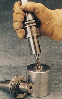
Figure 4: Once a new tool is inserted in the toolholder, the assembly is placed in a cooling block to draw the heat out of the toolholder.
The Shrink-Fitting Process
The key component of a shrink-fit toolholding system is the induction-heating unit. The solid-state, self-contained unit is slightly smaller than a refrigerator and costs $19,000 to $20,000. To change tools, the user places the toolholder in a receptacle built into a shelf in the front of the unit. An induction coil that sits beneath the shelf and encircles the collar of the toolholder heats the holder to expand its bore (Figure 3). Different sizes of induction coils are available to accommodate different toolholder diameters. The largest coil accepts toolholders designed for tool-shank diameters as large as 2".
In about 7 seconds, the heat expands the toolholder’s bore a few thousandths of an inch, enough for the user to remove the dull tool and insert a sharp one. The heat is localized at the collar around the tool, so a user wearing gloves can handle the toolholder by its shank and remove the tool mounted in the toolholder without fear of being burned. Once the new tool is in place, the user sets the assembly in a solid-aluminum cooling block, which draws heat from the heated area of the toolholder (Figure 4). Seconds after the assembly is placed in the block, the bore begins to shrink back to its original inner diameter, which is slightly smaller than the outer diameter (OD) of the tool shank. The resulting contraction exerts uniform pressure around the surface of the tool shank. The entire process, from the time the toolholder is inserted into the induction-heating unit to the time it is ready to be mounted once again into the machine tool, takes about 30 seconds.
The induction-heating unit gives the operator total control over the heating process. Larger toolholders, because their ODs are relatively close to the coil, are heated more efficiently by the unit, and thus, require less power to heat them to the proper temperature than smaller toolholders do. The heating unit’s controls allow the operator to vary power to regulate the amount of energy sent into the coil. A normal setting for tools from 1/4" through 1 1/2" in diameter is 70 percent of full power.
The unit also allows the operator to control the heating of the toolholder by adjusting the cycle time. The automatic control can be set to keep the heating unit on from 1 to 22 seconds. The normal cycle time is 7 seconds. By setting the unit for a short cycle time, the operator can keep the heat concentrated in the clamping area. The toolholder will be out of the unit and in the cooling block before the heat can travel to other parts of the toolholder. A guide is available that offers suggested cycle times and power settings based on the diameter of the toolholder, but some trial and error may be necessary to find a setting that ensures sufficient heat to open the bore of a toolholder without overheating it.
Once a shop has established the correct power and cycle settings for its toolholders, it can use the heating unit’s internal control to regulate the power to the coil and the cycle time. When the internal control is engaged, the front-panel controls are disengaged. This feature prevents users from sending too much power into the coil and overheating tools and toolholders, which may shorten the lives of these components. The operator can maintain even tighter control of the heating process by using an optional infrared sensor, which detects the amount of heat in the toolholder. When the toolholder reaches a preset temperature, the unit shuts off the power automatically.
The heating unit and toolholder are further protected by a hold-off cycle that automatically shuts down the machine for 12 to 15 seconds after the heating cycle. During this cycle, the unit pumps water through the coil to keep the coil at its standard operating temperature. It also prevents the operator from rapidly recycling the unit and overheating the toolholder.
Despite the use of heat to expand the toolholder, preserving the operator’s safety is relatively simple. The heated toolholder can be handled by an operator wearing leather or clean, dry cotton gloves. Because the heating unit uses electricity to heat the coil, the operator should stand on an approved rubber safety mat when using the equipment.
The unit requires little maintenance to assure its safe and effective operation. The operator or the shop’s maintenance personnel should visually inspect the induction coil four times a year to ensure that the equipment is in proper working order and insulation materials are in place.
Editor’s Note: This article includes material provided by Briney Toolholding Systems, Bad Axe, MI.
Related Glossary Terms
- centers
centers
Cone-shaped pins that support a workpiece by one or two ends during machining. The centers fit into holes drilled in the workpiece ends. Centers that turn with the workpiece are called “live” centers; those that do not are called “dead” centers.
- chatter
chatter
Condition of vibration involving the machine, workpiece and cutting tool. Once this condition arises, it is often self-sustaining until the problem is corrected. Chatter can be identified when lines or grooves appear at regular intervals in the workpiece. These lines or grooves are caused by the teeth of the cutter as they vibrate in and out of the workpiece and their spacing depends on the frequency of vibration.
- collet
collet
Flexible-sided device that secures a tool or workpiece. Similar in function to a chuck, but can accommodate only a narrow size range. Typically provides greater gripping force and precision than a chuck. See chuck.
- endmill
endmill
Milling cutter held by its shank that cuts on its periphery and, if so configured, on its free end. Takes a variety of shapes (single- and double-end, roughing, ballnose and cup-end) and sizes (stub, medium, long and extra-long). Also comes with differing numbers of flutes.
- gang cutting ( milling)
gang cutting ( milling)
Machining with several cutters mounted on a single arbor, generally for simultaneous cutting.
- high-speed steels ( HSS)
high-speed steels ( HSS)
Available in two major types: tungsten high-speed steels (designated by letter T having tungsten as the principal alloying element) and molybdenum high-speed steels (designated by letter M having molybdenum as the principal alloying element). The type T high-speed steels containing cobalt have higher wear resistance and greater red (hot) hardness, withstanding cutting temperature up to 1,100º F (590º C). The type T steels are used to fabricate metalcutting tools (milling cutters, drills, reamers and taps), woodworking tools, various types of punches and dies, ball and roller bearings. The type M steels are used for cutting tools and various types of dies.
- inner diameter ( ID)
inner diameter ( ID)
Dimension that defines the inside diameter of a cavity or hole. See OD, outer diameter.
- machining center
machining center
CNC machine tool capable of drilling, reaming, tapping, milling and boring. Normally comes with an automatic toolchanger. See automatic toolchanger.
- milling
milling
Machining operation in which metal or other material is removed by applying power to a rotating cutter. In vertical milling, the cutting tool is mounted vertically on the spindle. In horizontal milling, the cutting tool is mounted horizontally, either directly on the spindle or on an arbor. Horizontal milling is further broken down into conventional milling, where the cutter rotates opposite the direction of feed, or “up” into the workpiece; and climb milling, where the cutter rotates in the direction of feed, or “down” into the workpiece. Milling operations include plane or surface milling, endmilling, facemilling, angle milling, form milling and profiling.
- milling cutter
milling cutter
Loosely, any milling tool. Horizontal cutters take the form of plain milling cutters, plain spiral-tooth cutters, helical cutters, side-milling cutters, staggered-tooth side-milling cutters, facemilling cutters, angular cutters, double-angle cutters, convex and concave form-milling cutters, straddle-sprocket cutters, spur-gear cutters, corner-rounding cutters and slitting saws. Vertical cutters use shank-mounted cutting tools, including endmills, T-slot cutters, Woodruff keyseat cutters and dovetail cutters; these may also be used on horizontal mills. See milling.
- outer diameter ( OD)
outer diameter ( OD)
Dimension that defines the exterior diameter of a cylindrical or round part. See ID, inner diameter.
- shank
shank
Main body of a tool; the portion of a drill or similar end-held tool that fits into a collet, chuck or similar mounting device.
- shrink-fit toolholding
shrink-fit toolholding
Method of holding a round-shank cutting tool in a toolholder. To shrink-fit, the toolholder is heated in order to expand its bore, allowing a tool to be inserted. As the holder cools, the bore contracts around the shank to firmly hold the tool in place.
- toolholder
toolholder
Secures a cutting tool during a machining operation. Basic types include block, cartridge, chuck, collet, fixed, modular, quick-change and rotating.