Managing cutting tools and their associated costs is a difficult matter for all machine shops. Cutting tools directly impact cash flow, inventory cost, productivity and part quality, so proper tool selection and machining-process development can profoundly affect your business.
Of the common machining operations, such as milling, turning and sawing, holemaking is the most challenging for Mitsubishi Hitachi Power Systems Americas Inc. Gas turbines, like most machines, are assembled primarily with nuts and bolts. An MHPS gas turbine has a bill of material with 5,000 items, and most of these components are bolted together.
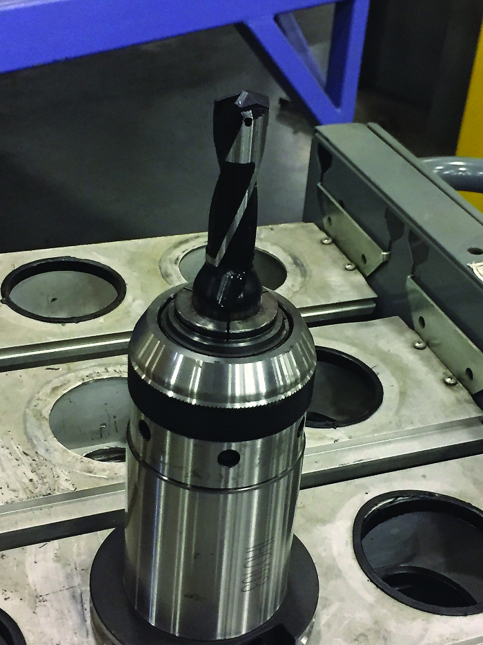
An example of the carbide-tipped drill for making holes in combustion components. This tool is more cost-effective than a solid-carbide drill that’s the same size. All images courtesy of C. Tate.
For many shops, a successful holemaking operation depends on selecting the correct combination of tools—drills, reamers, taps, boring bars, etc.—and applying them at the proper speeds and feeds. At MHPS, holemaking success is about timing—finding the best sequence in which to perform manufacturing operations.
Waterjet Cutting
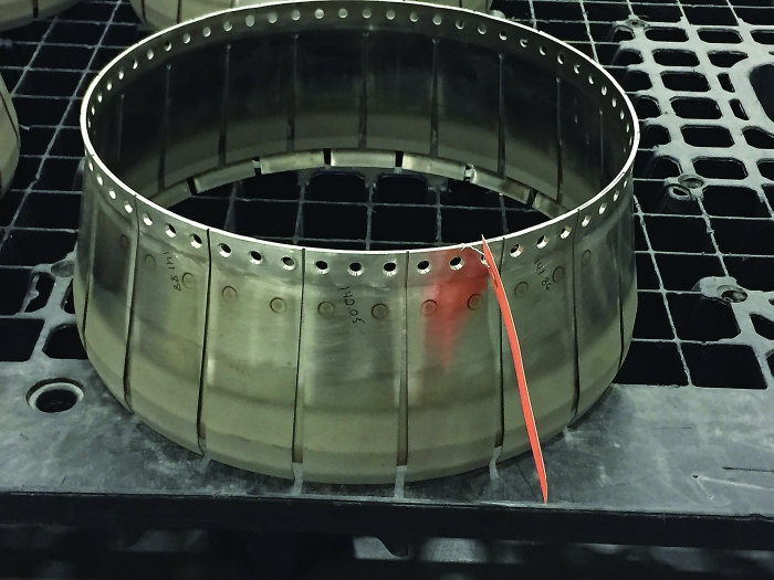
At MHPS, each combustion component must be cut from a flat sheet or plate before forming. Parts are then welded together. Combustion hardware is made from heat-resistant superalloys (HRSAs), like Inconel and Hastelloy, which make traditional cutting methods difficult.
Waterjet cutting has proven to be much more effective. We waterjet holes when the material is still flat and try to cut as many holes as possible on the flat-bed waterjet before forming the parts.
However, more than once we waterjet-machined holes in a flat blank only to see the forming process distort, tear or crack the material around the hole. All resulting defects must be repaired, or the part becomes scrap. So creating the holes at the correct time relative to other operations, like forming, is critical.
When we experience tearing or cracking of holes during the forming operations, we must change the order of operations so that holes are made after forming the part. Because we wanted to continue to utilize the waterjet process for these materials and mitigate issues when forming, we purchased a 5-axis waterjet that allows us to cut holes in parts that have been formed and welded together. The waterjet-holemaking process exerts less force on the workpiece than conventional drilling and facilitates use of workholding that is less complex and expensive than that needed for traditional machine tools.
MHPS’ 5-axis waterjet exerts little pressure on parts, which makes fixturing flimsy sheet metal parts easy.
Although waterjet cutting is the preferred method, it is not always suitable because of part size, configuration or accuracy requirements. In these cases, we are forced to use more traditional machining methods.
As a rule of thumb, we avoid waterjet cutting when the tolerances are closer than 0.250mm (0.010"). Final machining of an Inconel combustion duct is one such case. The duct must be machined after welding to ensure proper fit in the gas turbine.
We drill holes from 3mm (0.118") to 48mm (1.889") in diameter, and we have developed procedures for each size hole.
For holes up to 15mm (0.590"), we apply solid-carbide drills. As with all drilling operations, we select the shortest drill possible to enhance rigidity. Drills are mounted in an ER32 collet, but we use more accurate collet styles for our 3mm drills to minimize runout. A typical cutting speed in Inconel is 150 sfm (45.720 m/min.), and feed rates are selected based on drill size and the cutting tool manufacturer’s recommended chip load.
For holes from 15mm to 25mm (0.984"), we use an indexable drill that has a steel body and accepts a solid-carbide tip that screws onto the end of the body. This is the most reliable, cost-effective drill for our superalloys. This style of tool is more dependable than indexable drills that accept multiple inserts. Drills with multiple inserts have caused quality issues for us because of insert failure, resulting in catastrophic tool failure. However, tool availability dictates that we use indexable drills with multiple inserts on holes larger than 25mm in diameter.
Drilling HRSAs with a large tool is tricky; machines must be rigid and capable of producing lots of power. We have machines able to drive the tools, but our parts are formed from sheet metal, which can make the setup unstable, resulting in part movement, chatter or part deformation.
To help resolve stability issues associated with large drills, we have turned to helical milling. We typically drill a small pilot hole with a solid-carbide drill, then open the hole to the desired diameter with an endmill programmed to
cut in a helical path. This method allows us to control the amount of force exerted on the part because we can alter the DOC, unlike with a drill.
Rotor Components
Gas turbine rotor components also have numerous holes that must be machined. Our discs, for example, can have holes from 8mm (0.314") to 80mm (3.149") in diameter. In the combustion shop, the hole depth-to-diameter ratios are low, which works to our advantage when dealing with difficult-to-machine HRSAs. Rotor parts are made from easier-to-machine materials, but the holes have high depth-to-diameter ratios. Compounding the difficulty, many of these holes also have straightness and diameter tolerances that are very tight.
To make a large hole, we start with an indexable drill that has a solid-carbide point surrounded by small inserts. (It is a hybrid of the drills discussed earlier.) Because these tools have large diameter-to-length ratios, they tend to walk, creating holes that are not straight. Therefore, we install guide pads on the drill, which keep the tool from walking. Guide pads are made to closely fit the hole diameter. This makes the tool self-supporting and prevents walking.
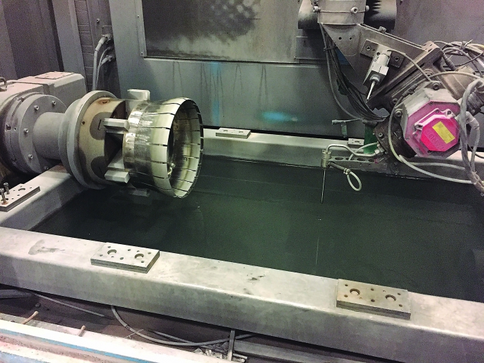
The waterjet lets the shop cut holes in parts that have been formed and welded together.
After drilling, a boring bar further enlarges the hole but also ensures that it is as straight as possible. Because the large indexable drills are expensive, sometimes we apply multiple boring bars to enlarge a hole, avoiding the need to purchase another drill.
After boring, we ream the hole with a high-performance reamer, which has an adjustable head that allows us to “dial” out any runout that could cause an out-of-tolerance condition. Reamer flutes are ground to be self-supporting, which, like the drill’s guide pads, keeps the tool from walking. Operating forces and temperatures experienced by the rotor
components, combined with poor surface finishes from machining, can initiate catastrophic material defects, like cracks. Therefore, we ream primarily to impart the finest surface finish.
MHPS has created processes for holemaking that work well for our shop. Like other shops, we continually seek better methods and tools so we can improve safety, quality, delivery and cost.
There is no universal “best way” to make holes, as each shop is different. One trait that shops that are proficient at holemaking do share, though, is a willingness to test innovative ideas and adopt best practices from industry.
Related Glossary Terms
- boring
boring
Enlarging a hole that already has been drilled or cored. Generally, it is an operation of truing the previously drilled hole with a single-point, lathe-type tool. Boring is essentially internal turning, in that usually a single-point cutting tool forms the internal shape. Some tools are available with two cutting edges to balance cutting forces.
- boring bar
boring bar
Essentially a cantilever beam that holds one or more cutting tools in position during a boring operation. Can be held stationary and moved axially while the workpiece revolves around it, or revolved and moved axially while the workpiece is held stationary, or a combination of these actions. Installed on milling, drilling and boring machines, as well as lathes and machining centers.
- chatter
chatter
Condition of vibration involving the machine, workpiece and cutting tool. Once this condition arises, it is often self-sustaining until the problem is corrected. Chatter can be identified when lines or grooves appear at regular intervals in the workpiece. These lines or grooves are caused by the teeth of the cutter as they vibrate in and out of the workpiece and their spacing depends on the frequency of vibration.
- collet
collet
Flexible-sided device that secures a tool or workpiece. Similar in function to a chuck, but can accommodate only a narrow size range. Typically provides greater gripping force and precision than a chuck. See chuck.
- cutting speed
cutting speed
Tangential velocity on the surface of the tool or workpiece at the cutting interface. The formula for cutting speed (sfm) is tool diameter 5 0.26 5 spindle speed (rpm). The formula for feed per tooth (fpt) is table feed (ipm)/number of flutes/spindle speed (rpm). The formula for spindle speed (rpm) is cutting speed (sfm) 5 3.82/tool diameter. The formula for table feed (ipm) is feed per tooth (ftp) 5 number of tool flutes 5 spindle speed (rpm).
- endmill
endmill
Milling cutter held by its shank that cuts on its periphery and, if so configured, on its free end. Takes a variety of shapes (single- and double-end, roughing, ballnose and cup-end) and sizes (stub, medium, long and extra-long). Also comes with differing numbers of flutes.
- feed
feed
Rate of change of position of the tool as a whole, relative to the workpiece while cutting.
- flat ( screw flat)
flat ( screw flat)
Flat surface machined into the shank of a cutting tool for enhanced holding of the tool.
- flutes
flutes
Grooves and spaces in the body of a tool that permit chip removal from, and cutting-fluid application to, the point of cut.
- gang cutting ( milling)
gang cutting ( milling)
Machining with several cutters mounted on a single arbor, generally for simultaneous cutting.
- milling
milling
Machining operation in which metal or other material is removed by applying power to a rotating cutter. In vertical milling, the cutting tool is mounted vertically on the spindle. In horizontal milling, the cutting tool is mounted horizontally, either directly on the spindle or on an arbor. Horizontal milling is further broken down into conventional milling, where the cutter rotates opposite the direction of feed, or “up” into the workpiece; and climb milling, where the cutter rotates in the direction of feed, or “down” into the workpiece. Milling operations include plane or surface milling, endmilling, facemilling, angle milling, form milling and profiling.
- reamer
reamer
Rotating cutting tool used to enlarge a drilled hole to size. Normally removes only a small amount of stock. The workpiece supports the multiple-edge cutting tool. Also for contouring an existing hole.
- sawing
sawing
Machining operation in which a powered machine, usually equipped with a blade having milled or ground teeth, is used to part material (cutoff) or give it a new shape (contour bandsawing, band machining). Four basic types of sawing operations are: hacksawing (power or manual operation in which the blade moves back and forth through the work, cutting on one of the strokes); cold or circular sawing (a rotating, circular, toothed blade parts the material much as a workshop table saw or radial-arm saw cuts wood); bandsawing (a flexible, toothed blade rides on wheels under tension and is guided through the work); and abrasive sawing (abrasive points attached to a fiber or metal backing part stock, could be considered a grinding operation).
- superalloys
superalloys
Tough, difficult-to-machine alloys; includes Hastelloy, Inconel and Monel. Many are nickel-base metals.
- turning
turning
Workpiece is held in a chuck, mounted on a face plate or secured between centers and rotated while a cutting tool, normally a single-point tool, is fed into it along its periphery or across its end or face. Takes the form of straight turning (cutting along the periphery of the workpiece); taper turning (creating a taper); step turning (turning different-size diameters on the same work); chamfering (beveling an edge or shoulder); facing (cutting on an end); turning threads (usually external but can be internal); roughing (high-volume metal removal); and finishing (final light cuts). Performed on lathes, turning centers, chucking machines, automatic screw machines and similar machines.
- waterjet cutting
waterjet cutting
Fine, high-pressure (up to 50,000 psi or greater), high-velocity jet of water directed by a small nozzle to cut material. Velocity of the stream can exceed twice the speed of sound. Nozzle opening ranges from between 0.004" to 0.016" (0.l0mm to 0.41mm), producing a very narrow kerf. See AWJ, abrasive waterjet.
Author

Christopher Tate is the owner of Tate Engineering, a Natchez, Mississippi, firm that helps manufacturers solve efficiency problems. Tate, who earned master's degree in industrial technology from Mississippi State University, has 32 years of experience in the metalworking industry.