Shifting gears

Author Aaron Habeck
Published
February 01, 2013 - 10:30am

Joining flexibility with high productivity when gear milling.

Imagine a gear milling method where the toolpath—not the tool shape—determines gear characteristics such as diametral pitch or pressure angle. A new concept, involute milling, provides that functionality while delivering machining efficiency and production versatility. The result is a “democratization” of gear milling, moving the process from single-purpose, dedicated machine tools to multipurpose machines that can produce small batches economically because no costly hobs or gashers are needed.

120296.tif

All images courtesy Sandvik Coromant

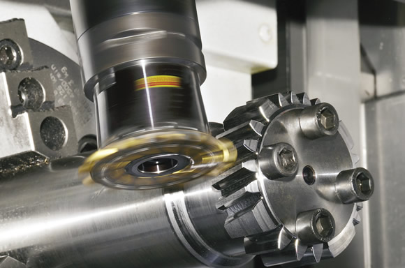
Involute milling, or InvoMilling, uses standard mill/turn machines and off-the-shelf cutting tools to produce small to medium-sized batches of spur and helical gears.

Gear making typically involves custom orders. Said one manager at a gear milling company: “We specialize in helical and spur gear wheels for a range of different industries, with many machined to specific customer requirements. A customer may want a specific gear wheel, batch of gear wheels or components for automobile transmissions. We mostly produce from one to 100 components, but we also have production orders for up to 2,000 gear wheels throughout a year. Just-in-time deliveries are the norm for some products, particularly when it comes to components for vehicle gearboxes.”

Until recently, this type of production scenario meant the gear maker would have to lock into using special, one-off gear-making tools for each project to produce high volumes. However, creating new tooling and programming for each gear wheel is costly.

Outside the Box

The new gear milling approach is based on using a multiaxis mill/turn machine. Sandvik Coromant Co. developed involute milling and it is being offered in collaboration with DMG / Mori Seiki USA Inc. Involute milling, or InvoMilling, is an alternative to the specialized hobbing process traditionally used to make gears. For gears with 25 to 30 teeth, InvoMilling’s cycle time is comparable to single-start hobbing with HSS tools. However, the possibility to integrate many operations in one setup and on one machine can reduce overall cycle times. Also, the wait time for a new gear hob can be weeks, while acquiring a new CNC InvoMilling code takes a matter of hours.

In this multiaxis gear-milling process, multipurpose machines are fitted with tools composed of off-the-shelf inserts for making spur and helical gears. It can produce spur and helical gears using a disc-shaped milling cutter tooled with grooving inserts. With simultaneous motion of the X and B axes or the Y and B axes, the tool follows an involute path. Consequently, variations in gear shape are produced according to the toolpath—not the shape of the tool. For this purpose, mill/turn machines are ideal.

120294.tif

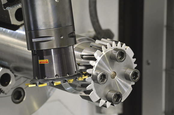
When involute milling the tooth space of an outer spur gear, a groove is facemilled in an axial direction on the workpiece. For the following cuts, the gear wheel rotates slightly, coordinating with the simultaneous radial plunging of the InvoMilling tool, creating an involute curve shape.

It is now possible to program in the MORI-AP conversational software for InvoMillng processes, which is available for DMG / Mori Seiki Model NT mill/turn centers. The flexible B-axis with ±120° rotation range, the high speed and precision of the direct-drive motor and the indexing capability of 0.0001° allows production of gears with up to a DIN 6 quality.

Gear hobbing has traditionally been performed on a dedicated machine, which also can produce other transmission components. However, due to its lack of flexibility, hobbing is not the optimal solution when many different types or small batches of gear wheels need to be produced.

InvoMilling is a combination of slot milling and turn milling. It enables machining of gears of any helix angle—both involute and noninvolute profiles—with the same tools. This series illustrates the process.

Step 1: slot milling.

123043.tif

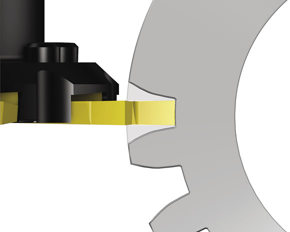
Steps 2 and 3: machining the root and protuberance.

123102.tif

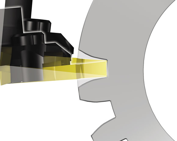
Step 4: turn milling the lower gear tooth profile.

123103.tif

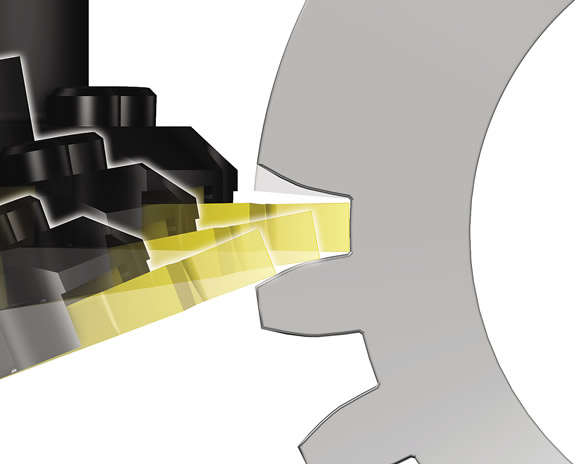
Step 5: turn milling the upper gear tooth profile.

123104.tif

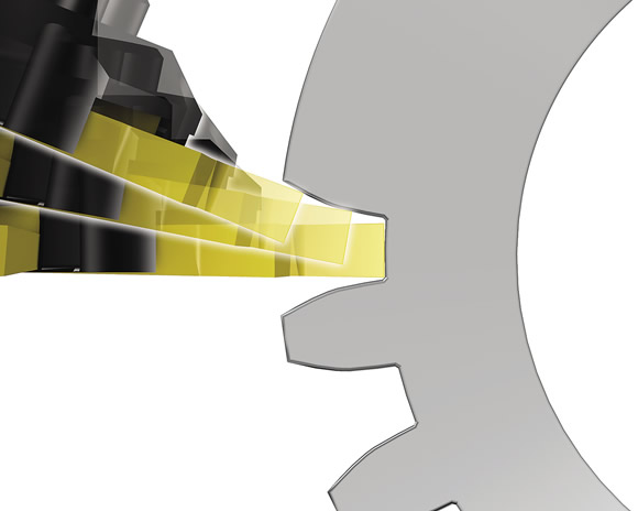
Step 6: finished tooth space.

123105.tif

InvoMilling software for the NT machine immediately enables manufacturing different types of gear wheels. Gear-making cutter kits with three tools—CoroMill 161, Coro-Mill 162 size 4 and CoroMill 162 size 6—cover the range from module 2 to 12, or 12 to 2 DP (diametral pitch).

The price of a kit is similar to that of one dedicated inserted hob. The kit can be used to produce a range of modules, while the hob can only produce one single module, albeit more quickly.

Involute milling is a combination of slot milling and turn milling. It machines gears with any helix angle—both involute and noninvolute profiles—with the same tools. The number of cuts involved depends on the size of the gear and the size of the cutters being applied.

This method makes use of the advanced machine control and high accuracy of the NT mill/turn machine and the cutters to make finished gears on the machine as well as semifinished gears to be ground on a separate machine. Applying the latest developments in insert grades has also enabled a high level of cutting data to be applied for optimal efficiency.

In addition, chamfers at the gear tooth’s OD can be machined during involute milling, as well as protuberance angles, profiles and radii at the tooth’s base. The cutting forces with this process are considerably smaller than with hobbing, so larger tooth forms can be made in smaller machines.

For example, when involute milling the tooth space of an outer spur gear, a groove is milled in the axial direction on the workpiece. In the following cuts, the gear wheel rotates slightly, coordinating with the simultaneous radial plunging of the cutting tool, producing an involute curve shape. For larger gear modules, more cuts may be necessary. For wider gears, the cutter is offset in the axial direction and the procedure is repeated.

120173.tif
120169.tif

Involute milling can produce spur and helical gears using dedicated milling cutters, such as CoroMill 161 (top) and two sizes of CoroMill 162 (above), which together cover modules 2 to 12.

Involute milling offers several key advantages. Because each cutting tool covers several gear modules, overall tool costs for small to medium-sized batches are lower than comparable hobbing processes. Also, lead time is not an issue, while hobbing tool lead times can be 8 to 12 weeks.

One disadvantage of involute milling is that it is somewhat limited for larger gear modules, but the process has been used to produce up to and including a module 18 gear wheel with a diameter of 800mm.

Another manufacturing process used to make gears, endmilling, is flexible but slow. Involute milling combines the speed of disc cutting with the flexibility of endmilling, and, all things considered, can be up to 10 times faster than using endmills for gear manufacturing.

Indexable Inserts

Modern indexable-insert technology makes this new gear milling method possible because the positive geometry on each insert generates low cutting forces, enabling a high level of cutting data to be used while ensuring accurate profiles for close tolerance ranges. With involute milling, gear teeth with quality level 6, DIN 3962 or better can be achieved. Moreover, surface finishes finer than 3µm Rz can be achieved through the correct application of tools in sufficiently rigid machines.

In addition to producing gears to quality levels comparable to hobbing, involute milling can generate various gear grinding allowances. That is to say, material can be left on the gear flanks that can then be ground away to obtain gears with very accurate shape and surface finish.

Cycle time for involute milling gear modules 4 to 10 is, when the number of teeth is below 30, comparable to single-start hobbing with HSS tools. Because many operations can be integrated in the multitask machine, the gear can often be finished in one setup. This results in short lead times and changeovers, and, consequently, improved work-in-progress levels for production of one-offs and small and medium-sized batches.

Due to these efficiencies, even in cases where the cycle time for involute milling is longer than for hobbing, total manufacturing time is shorter. Because there is no waiting time for a dedicated tool to be made, production can start immediately after a new setup is completed.

Involute milling represents a real technology shift, providing significant improvements in cost, flexibility and lead time while using advanced multitask machine tools to manufacture high-quality gears. CTE

About the Author: Aaron Habeck is marketing project manager for Sandvik Coromant Co., Fair Lawn, N.J. For more information about the company’s InvoMilling process, call (800) SANDVIK or visit www.sandvik.coromant.com/us.

Related Glossary Terms

  • centers

    centers

    Cone-shaped pins that support a workpiece by one or two ends during machining. The centers fit into holes drilled in the workpiece ends. Centers that turn with the workpiece are called “live” centers; those that do not are called “dead” centers.

  • computer numerical control ( CNC)

    computer numerical control ( CNC)

    Microprocessor-based controller dedicated to a machine tool that permits the creation or modification of parts. Programmed numerical control activates the machine’s servos and spindle drives and controls the various machining operations. See DNC, direct numerical control; NC, numerical control.

  • endmilling

    endmilling

    Operation in which the cutter is mounted on the machine’s spindle rather than on an arbor. Commonly associated with facing operations on a milling machine.

  • gang cutting ( milling)

    gang cutting ( milling)

    Machining with several cutters mounted on a single arbor, generally for simultaneous cutting.

  • grinding

    grinding

    Machining operation in which material is removed from the workpiece by a powered abrasive wheel, stone, belt, paste, sheet, compound, slurry, etc. Takes various forms: surface grinding (creates flat and/or squared surfaces); cylindrical grinding (for external cylindrical and tapered shapes, fillets, undercuts, etc.); centerless grinding; chamfering; thread and form grinding; tool and cutter grinding; offhand grinding; lapping and polishing (grinding with extremely fine grits to create ultrasmooth surfaces); honing; and disc grinding.

  • grooving

    grooving

    Machining grooves and shallow channels. Example: grooving ball-bearing raceways. Typically performed by tools that are capable of light cuts at high feed rates. Imparts high-quality finish.

  • high-speed steels ( HSS)

    high-speed steels ( HSS)

    Available in two major types: tungsten high-speed steels (designated by letter T having tungsten as the principal alloying element) and molybdenum high-speed steels (designated by letter M having molybdenum as the principal alloying element). The type T high-speed steels containing cobalt have higher wear resistance and greater red (hot) hardness, withstanding cutting temperature up to 1,100º F (590º C). The type T steels are used to fabricate metalcutting tools (milling cutters, drills, reamers and taps), woodworking tools, various types of punches and dies, ball and roller bearings. The type M steels are used for cutting tools and various types of dies.

  • just-in-time ( JIT)

    just-in-time ( JIT)

    Philosophy based on identifying, then removing, impediments to productivity. Applies to machining processes, inventory control, rejects, changeover time and other elements affecting production.

  • milling

    milling

    Machining operation in which metal or other material is removed by applying power to a rotating cutter. In vertical milling, the cutting tool is mounted vertically on the spindle. In horizontal milling, the cutting tool is mounted horizontally, either directly on the spindle or on an arbor. Horizontal milling is further broken down into conventional milling, where the cutter rotates opposite the direction of feed, or “up” into the workpiece; and climb milling, where the cutter rotates in the direction of feed, or “down” into the workpiece. Milling operations include plane or surface milling, endmilling, facemilling, angle milling, form milling and profiling.

  • milling cutter

    milling cutter

    Loosely, any milling tool. Horizontal cutters take the form of plain milling cutters, plain spiral-tooth cutters, helical cutters, side-milling cutters, staggered-tooth side-milling cutters, facemilling cutters, angular cutters, double-angle cutters, convex and concave form-milling cutters, straddle-sprocket cutters, spur-gear cutters, corner-rounding cutters and slitting saws. Vertical cutters use shank-mounted cutting tools, including endmills, T-slot cutters, Woodruff keyseat cutters and dovetail cutters; these may also be used on horizontal mills. See milling.

  • outer diameter ( OD)

    outer diameter ( OD)

    Dimension that defines the exterior diameter of a cylindrical or round part. See ID, inner diameter.

  • pitch

    pitch

    1. On a saw blade, the number of teeth per inch. 2. In threading, the number of threads per inch.

  • tolerance

    tolerance

    Minimum and maximum amount a workpiece dimension is allowed to vary from a set standard and still be acceptable.

Author

Aaron Habeck is marketing project manager for Sandvik Coromant Co., Fair Lawn, N.J. For more information about the company’s InvoMilling process, call (800) SANDVIK or visit www.sandvik.coromant.com/us.