The debate about roller-type linear guide ways vs. conventional box ways has raged for decades. Linear guide ways are fast, accurate and relatively easy to install in both high-end and low-cost, commodity machine tools. Proponents say linear guide ways create less heat and friction and don’t have the stick-slip action associated with box-style ways, which should make them more accurate. Linear guide ways are commonly found on many high-speed machining centers and Swiss-style lathes, where lightning fast rapid-traverse rates and light cuts are the rule.
On the other hand, old as the Industrial Revolution itself, box ways are known for their ability to carry heavy loads and take heavy cuts. They have superior vibration damping ability, but require a master craftsman to install. Compared to linear guide ways, box ways are less likely to be damaged in a crash, and, in most cases, offer longer service life. They, too, can be extremely accurate and are often used in jig boring, grinding and other machine tools that require submicron precision.

VIDEO
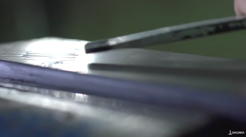
View a hand scraping video supplement courtesy Okuma America.
Big Business
While the argument about which is better won’t be settled anytime soon, both styles of guide ways should be appropriately sized for the machine tool, of sufficient quality for the application and properly installed. Poorly designed or improperly installed guide ways—box or linear—will doom even the best-designed machine tool, regardless of technological merits. For machine builders and service companies alike, one aspect of guide way selection is especially important: Box ways can take some serious elbow grease to scrape and substantial skill to install.
“For a large machine, it can easily take several weeks to scrape the ways,” said Scott Ashworth, president of capital equipment sales and service company KRC Machine Tool Services, Independence, Ky. KRC is rebuilding a boring mill, with an approximate 8’-long (2.44m) table and two bearing surfaces that are each 6” (152.4mm) across. “Even with two guys tag-teaming the work, it takes a long while to complete a project this size.”
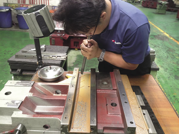
Knowing where to scrape and how much to remove takes years of experience. Image courtesy KING-WAY Scraping Consultants.
Ashworth said a substantial percentage of his business is the remanufacturing and retrofitting of old, heavy-duty machines, such as horizontal boring mills and vertical turret lathes. Many have nonfriction material, such as Turcite or Rulon, on the way surfaces. These materials increase the weight capacity of machine tools while reducing the tendency of precision load-bearing surfaces to “stick” together.
Ashworth explained that hand scraping creates small pockets on the surface to hold oil and provide lubrication, but, even with a properly scraped surface, some metal-to-metal friction occurs. Because of this, when the ballscrew is first turned, there’s a small amount of “windup” until the machine starts moving, at which point it tends to jump forward. “Granted, this is a very minute distance—microns, perhaps—but it can be an important factor with very fine, detailed machining and heavy loads,” he said. “This is why many builders opt for Turcite.”
Turcite and comparable nonfriction way surfaces are made of polytetrafluoroethylene (PTFE), a thermoplastic that is often blended with bronze and other additives before being “skived” into sheets 12” to 24” wide × ¼”, or less, thick (304.8mm to 609.6mm × 6.35mm). It is glued to the cast iron or steel substrate, then scraped in the same manner as metal box ways to create oil-bearing surfaces. This ubiquitous material offers a frictional coefficient roughly 20 percent that of scraped metal-on-metal ways.
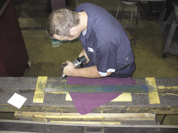
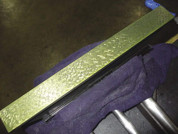
A technician (top) power scrapes the high spots on a metal way surface. A finished way (below) is ready for installation. Images courtesy Busch Precision.
A Lasting Legacy
Whether metal or plastic, hand scraping requires application of a flat, carbide-tipped blade, to make the way flat, and then “flaking” the finished surface. The following six steps describe the process:
1. Make an initial “cross scrape” to clean and prepare the surface.
2. Remove any loose chips and dust, then apply a small amount of mineral oil and “stone” the surface to remove burrs.
3. Apply a thin layer of bluing paste to the surface.
4. Rub the way on a surface plate, which removes the colored paste from the high spots.
5. Scrape the high spots, then repeat steps 2 through 4 until the surface is completely flat and the machine’s geometric requirements are met.
6. Flake the surface to create oil pockets, then clean and stone it one final time.
Bob Behnke, a machinist at Busch Precision Inc., a Milwaukee contract manufacturer and machine repair company, said scrape marks are like fingerprints of the person who worked on the machine. “Everybody has their own individual pattern. Over time, you look at enough of them and you’re able to recognize who did the work. We have people who scraped here 25 years ago, and I can still pick out which machines were theirs.”
Behnke said the amount of scraping, the depth of each individual mark and the distance between them (points per square inch) depends on a number of factors. A very worn machine could require grinding or machining to true the geometry, followed by a complete scrape job. A light rebuild may only need to be “freshened up” to make surfaces flat and create the proper amount of oil retention. Machines that will see heavy loads call for deep scraping, where light-duty machines can be effective with shallower scrapes. In each case, the craftsman follows the same basic process, but makes technique adjustments based on skill level, experience and the application needs of the machine tool.
“There’s a lot to it,” Behnke said. “The length of time spent scraping any particular surface or machine comes down to how many high spots there are to begin with, how much resistance is acceptable when the machine tool traverses back and forth, the amount of lubrication that’s needed and the size of the way surface. It takes a lot of experience, but it’s also physically demanding. You have to push on the blade and really dig in if you’re going to get a deep scrape, which is the best way to assure longevity in the machine tool.”
Sticking to the Plan
Aside from strong forearms and a steady grip, successful scrapers have a solid game plan. “You can’t just go at it randomly,” Behnke said. “You have to be very meticulous, scraping first in one direction, then the other. That breaks up the lines and gives a nice, uniform pattern.”
Okuma America Corp. Applications Engineer Robbie Williams agrees. The Charlotte, N.C., machine builder hand-scrapes wherevertwo moving metal surfaces meet to reduce the wear and tear on machine tools. “You can turn the machine off and walk away from it for weeks, and when you turn it back on again, you’ll still have that oil in there,” he said. “Because of this, there’s never any actual metal-to-metal contact.”
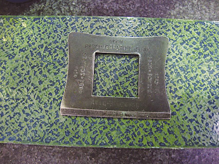
Measuring the points per inch on a scraped Rulon142 wear strip. Image courtesy KING-WAY Scraping Consultants.
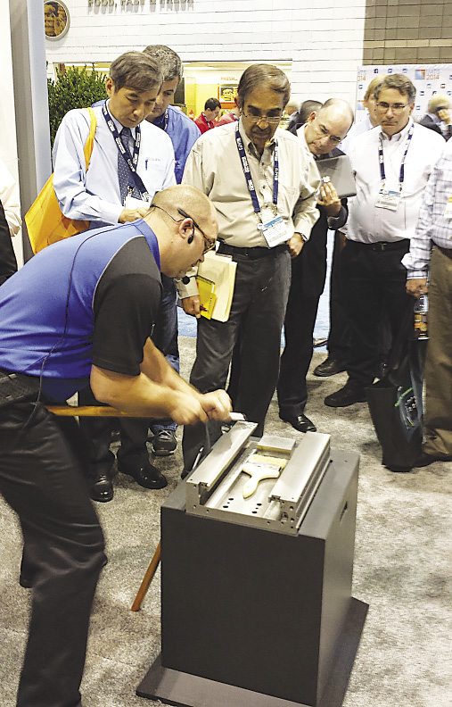
Robbie Williams, applications engineer for Okuma America, conducts an in-booth hand scraping seminar at IMTS. Image courtesy Okuma America.
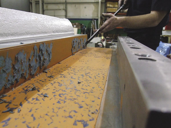
Part of the machine rebuilding process involves cleaning all surfaces and removing old paint and grime. Image courtesy KRC Machine Tool Services.
The challenges of scraping rise exponentially as machines become larger. Williams said a small lathe might take 10 to 30 hours to complete, whereas a horizontal machining center can take far longer. That’s because more things can go wrong as the machine size increases—ways might be concave or convex and can twist from one end to the other. All geometric irregularities must be removed so the surfaces mate perfectly through careful, patient scrapes with a carbide blade.
Williams has been scraping for 16 years, but said he still learns new things every day. He teaches a weeklong class on hand scraping at York Technical College and has conducted in-booth seminars at IMTS. Becoming proficient at hand scraping takes several years as an apprentice, he said, working under the tutelage of a journeyman scraper.
Tools of the Tradesman
One such journeyman is Richard King, who learned the art of hand scraping from his father and has passed down what he learned to more than 20,000 students. The owner of KING-WAY Scraping Consultants Inc., Cottage Grove, Minn., King said his profession is a lot like detective work. “Say you have a machine that’s been running the same production job over and over again. Naturally, it’s going to wear out in one area and have to be rebuilt. At that point, you have to take it apart, clean it and inspect every component before scraping anything.”
King added that the process begins with leveling the machine to factory specifications. The weight of the toolchanger or turret, the electrical cabinet hanging off the back, the spindle cartridge all impact the pitch and yaw of the machine tool and must be accounted for when scraping the machine ways back to square. King said most builders recommend laser leveling their machines, but a high-quality set of levels can achieve similar results in the right hands.
“Once the machine is level, you’ll need a scraper, some nondrying bluing paste, a precision surface plate and a set of straight edges,” he said. “We recommend power scraping, because it’s much faster than hand scraping and—if used properly—achieves better results.” (See sidebar below.)
King said the comparison between hand scraping and power scraping is little different than drilling a hole with a hand drill vs. an electric one. He admits power scraping takes a different approach and can be overdone, but that’s all part of the learning process. However it’s done, scraping is just a small part of building or rebuilding machine tools. “It’s a very important part, but is probably only 25 percent of the total picture,” he said. “The rest involves fitting the pieces together properly, cleaning and refurbishing and restoring the mechanics of the machine tool. Still, there’s a lot more to scraping than just making a flat surface. Knowing where to scrape and how much to remove takes years of experience. It’s definitely a skilled trade.”

Power up
Matt Milhomens, inside technical sales at DAPRA Corp., Bloomfield, Conn., said power scraping is at least twice as fast as manual scraping.
“We did time studies at General Motors. One guy’s productivity went up by 54 percent, another went up 76 percent. It doesn’t matter if you’re a small person or someone with huge muscles, power scraping eliminates a ton of hard work,” Milhomens said.
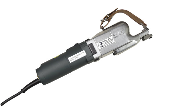
The BIAX power scraper offers adjustable stroke length and speed. Image courtesy DAPRA.
The BIAX power scraper was invented in the early 1950s by Walter Wetzel, brother of DAPRA’s owner, Rudi Wetzel. It incorporates an electric motor to drive a reciprocating carbide-tipped blade, mimicking the back and forth motion of hand scraping. The blade speed and stroke is adjustable—up to 1,900 strokes per minute, with stroke lengths from 0” to 0.8” (20mm). Milhomens said operating the BIAX is about as difficult as steering a bicycle. All that’s required is to set the proper stoke and speed, and then push. Long, fast strokes are suitable for roughing and heavy material removal, whereas short, delicate strokes flake the finished surface or get into tight corners.
“We’ve sold [power scrapers] to companies all over the world, from machine builders and reconditioners, to manufacturing companies that rebuild their own machines in-house,” Milhomens said. “Even the folks who’ve been hand scraping for years like how easy the BIAX operates. There are none of the aches and pains you get from gripping a blade all day long, and the cutting method can be customized to your own personal preference.”
The price for a BIAX scraper is from $2,700 to $3,500, inexpensive enough that even some hobbyists purchase one. Milhomens admits that hand scraping is never going away, and is preferred by many for finishing and fine detail work, but power scraping will at least do most of the heavy lifting. “It just makes life a lot simpler.”
—K. Hanson
Contributors
Busch Precision Inc.
(414) 362-7300
www.buschprecision.com
DAPRA Corp.
(800) 243-3344
www.dapra.com
KING-WAY Scraping Consultants Inc.
(844) 833-6334
www.handscraping.com
KRC Machine Tool Services
(888) 4-KRC-MTS
www.krcmachinetoolservices.com
Okuma America Corp.
(704) 588-7000
www.okuma.com/americas
Related Glossary Terms
- boring
boring
Enlarging a hole that already has been drilled or cored. Generally, it is an operation of truing the previously drilled hole with a single-point, lathe-type tool. Boring is essentially internal turning, in that usually a single-point cutting tool forms the internal shape. Some tools are available with two cutting edges to balance cutting forces.
- centers
centers
Cone-shaped pins that support a workpiece by one or two ends during machining. The centers fit into holes drilled in the workpiece ends. Centers that turn with the workpiece are called “live” centers; those that do not are called “dead” centers.
- flat ( screw flat)
flat ( screw flat)
Flat surface machined into the shank of a cutting tool for enhanced holding of the tool.
- grinding
grinding
Machining operation in which material is removed from the workpiece by a powered abrasive wheel, stone, belt, paste, sheet, compound, slurry, etc. Takes various forms: surface grinding (creates flat and/or squared surfaces); cylindrical grinding (for external cylindrical and tapered shapes, fillets, undercuts, etc.); centerless grinding; chamfering; thread and form grinding; tool and cutter grinding; offhand grinding; lapping and polishing (grinding with extremely fine grits to create ultrasmooth surfaces); honing; and disc grinding.
- jig
jig
Tooling usually considered to be a stationary apparatus. A jig assists in the assembly or manufacture of a part or device. It holds the workpiece while guiding the cutting tool with a bushing. A jig used in subassembly or final assembly might provide assembly aids such as alignments and adjustments. See fixture.
- jig boring
jig boring
High-precision machining (a sophisticated form of milling) that originally pertained to jig and fixture manufacturing. Basic jig-boring processes include centering, drilling, reaming, through and step boring, counterboring and contouring.
- lathe
lathe
Turning machine capable of sawing, milling, grinding, gear-cutting, drilling, reaming, boring, threading, facing, chamfering, grooving, knurling, spinning, parting, necking, taper-cutting, and cam- and eccentric-cutting, as well as step- and straight-turning. Comes in a variety of forms, ranging from manual to semiautomatic to fully automatic, with major types being engine lathes, turning and contouring lathes, turret lathes and numerical-control lathes. The engine lathe consists of a headstock and spindle, tailstock, bed, carriage (complete with apron) and cross slides. Features include gear- (speed) and feed-selector levers, toolpost, compound rest, lead screw and reversing lead screw, threading dial and rapid-traverse lever. Special lathe types include through-the-spindle, camshaft and crankshaft, brake drum and rotor, spinning and gun-barrel machines. Toolroom and bench lathes are used for precision work; the former for tool-and-die work and similar tasks, the latter for small workpieces (instruments, watches), normally without a power feed. Models are typically designated according to their “swing,” or the largest-diameter workpiece that can be rotated; bed length, or the distance between centers; and horsepower generated. See turning machine.
- machining center
machining center
CNC machine tool capable of drilling, reaming, tapping, milling and boring. Normally comes with an automatic toolchanger. See automatic toolchanger.
- milling machine ( mill)
milling machine ( mill)
Runs endmills and arbor-mounted milling cutters. Features include a head with a spindle that drives the cutters; a column, knee and table that provide motion in the three Cartesian axes; and a base that supports the components and houses the cutting-fluid pump and reservoir. The work is mounted on the table and fed into the rotating cutter or endmill to accomplish the milling steps; vertical milling machines also feed endmills into the work by means of a spindle-mounted quill. Models range from small manual machines to big bed-type and duplex mills. All take one of three basic forms: vertical, horizontal or convertible horizontal/vertical. Vertical machines may be knee-type (the table is mounted on a knee that can be elevated) or bed-type (the table is securely supported and only moves horizontally). In general, horizontal machines are bigger and more powerful, while vertical machines are lighter but more versatile and easier to set up and operate.
- pitch
pitch
1. On a saw blade, the number of teeth per inch. 2. In threading, the number of threads per inch.
- toolchanger
toolchanger
Carriage or drum attached to a machining center that holds tools until needed; when a tool is needed, the toolchanger inserts the tool into the machine spindle. See automatic toolchanger.
Author

Kip Hanson is a contributing editor for Cutting Tool Engineering magazine. Contact him by phone at (520) 548-7328 or via e-mail at [email protected].