When turning long parts, the traditional workholding technique is to chuck one end of the part and support the other end with a live or dead center. This is generally effective but has two drawbacks. First, the part must be reversed (double-ended) to machine the end gripped by the chuck jaws, and, even when expertly done, rechucking can lead to taper and diminished concentricity in the part. Second, the time associated with double-ending and changing chuck jaws increases machine downtime, particularly when small batches with differing diameters require frequent setups.
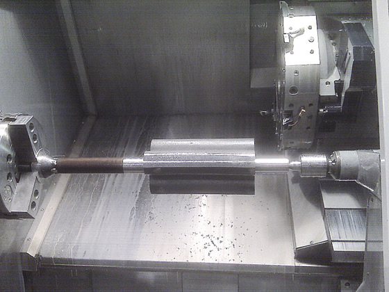
Face driving is a viable alternative when these drawbacks have a noticeable effect on production efficiency. Rather than clamping onto a surface to be machined, a face driver locates on the end face of the part. Chisel-edged drive pins penetrate the end face while a center point locates the part on center. The single-axis reference point established by the center point allows for a high degree of accuracy. By machining the entire surface in a single operation between centers, concentricities as accurate as 0.0004" to 0.0008" (0.0102mm to 0.0203mm) TIR are possible.
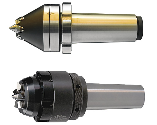
Figure 1. Mechanical face drivers allow quick changeout of drive pins and center points and deliver accuracies from 0.0004" to 0.0008" TIR. Hydraulic designs are better suited to roughing applications because their accuracies are from 0.0015" to 0.0024" TIR.
Face drivers are suitable for many between-center operations, including hobbing, milling, shaping, gear cutting, spline milling, facing, turning and grinding. Drivers are offered in two styles: mechanical and hydraulic (Figure 1).
Direct or Soft-Jaw Mounting
The face driver can be directly mounted, replacing the chuck, or chucked in soft jaws. Of these two options, direct mounting is the most accurate, because it minimizes part runout. The first step is to mount a spindle adapter to the machine spindle. The face driver is then mounted to the spindle adapter (Figure 2). The adapter has stirring screws, which allow a machinist to adjust the position of the face driver center point until it rotates as close to zero TIR as possible. This eliminates any induced runout associated with chucking the driver in soft jaws.
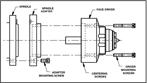
Figure 2. Direct mounting of a face driver using a spindle adapter.
With proper selection, one face driver can be used to run a broad range of parts of various diameters and lengths. The key factor is the diameter of the circle formed by the drive pins, known as the driving, or gripping, diameter (Figure 3). The part diameter should be no more than three times the gripping diameter, and the part length should not exceed 15 times the gripping diameter.
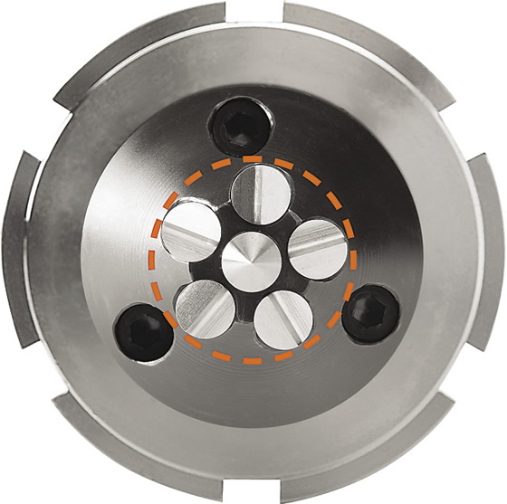
Figure 3. The gripping diameter is the diameter of the circle that touches the outside edges of the drive pins.
To illustrate, let’s assume the drive pins have a gripping diameter of 1" (25.4mm). Consequently, these pins can turn a part up to 3" (76.2mm) in diameter and up to 15" (381mm) in length. To increase system flexibility, each driver comes with three sets of drive pins that grip at different diameters. In our example, this driver would come with drive pins that grip at 1", 1.2" (30.5mm) and 1.4" (35.6mm) in diameter. Each set of drive pins can turn larger and longer parts based on their respective gripping diameters.
Parts can be loaded and clamped in seconds, both manually and automatically. Load and unload times are consistently faster than using drive dogs or chucks. Changing drive pins and center points takes less than a minute. The repetitive nature of the process, with the part held securely between centers, also lends itself to automation. All this adds up to higher throughput, less downtime and more productivity.
Turning to Face Drivers
In turning applications, face drivers can grip a variety of work materials. The most common material types are forgings and bar stock. Brass, aluminum, low-carbon steel and other “soft” metals with hardnesses typically less than 40 HRC are easily turned with a standard face driver. Hard turning can also be accomplished on metals with hardnesses from 40 to 65 HRC, including tool steels and other high-tensile-strength alloys. To ensure sufficient gripping force, carbide-tipped or diamond-plated drive pins are recommended.
Face drivers not only support a workpiece, but can position it using the indexing function of the machine spindle. When turning with live tooling, the part can be machined, then stopped to allow drilling, milling of flats and keyways, and similar tasks, all in a single operation. End users also report turning various nonmetal materials with face drivers, such as plastics, graphite, composites—even silicon rods that are subsequently sliced into electronic wafers.
Grinding typically involves hardened materials and, as in hard turning, carbide-tipped or diamond-plated drive pins should be used. This assumes the grinder provides sufficient tailstock force to seat the drive pins, which, unfortunately, is often not the case. Many small cylindrical grinders utilize spring-loaded tailstocks, which do not provide sufficient force. Hydraulic tailstocks are more common on large grinders.
Tailstock Force is Key
As with many workholding applications, tailstock force is critical. It could well be that your machine is already delivering the proper amount of tailstock force. This can be checked during the initial setup by clamping the part, engaging the driver, removing the part and measuring the depth of the drive pin indentations. The witness marks should be 0.003" to 0.005" (0.076mm to 0.127mm) deep and of equal size and shape. If so, tailstock force is sufficient (Figure 4). If not, the tailstock force needs to be adjusted until the pin marks are sufficiently deep and uniform. This is where it gets complicated.
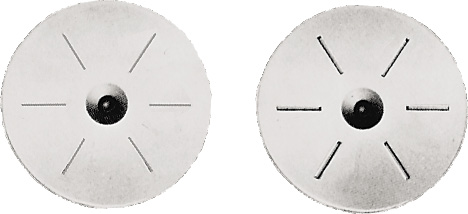
Figure 4. Penetration of the drive pins should be uniform after initial clamping (left) and sufficiently deep after final clamping (right) to assure an equal grip by each pin during machining.
Two pieces of information are required, the first being the amount of force needed to machine a part without slippage or binding. The force (measured in pounds) applied by the machine’s tailstock must be sufficient for the drive pins to penetrate firmly into the face of the workpiece. Riten has published tables to help users determine the proper force for a particular operation. Force calculation is based on factors such as workpiece diameter, gripping diameter of the drive pins, DOC, feed rate and material hardness.
The second piece of information is how much force your machine provides. Unfortunately, lathes and grinders may not display the actual pounds of force applied by the tailstock. Typically, a lathe will employ either a hydraulic or servodriven tailstock. Hydraulic tailstocks produce a constant force against the driven part. These tailstocks have gages that measure system pressure in PSI or a similar unit. Pressure and force are related but are not the same.
Some newer machines have a servodriven tailstock that can present problems if the force applied varies from moment to moment. Servomotor controls typically display a percentage of load, but not the actual applied force.
In either case, users need a conversion chart to switch from pressure and/or percent of load to the actual applied force. The machine builder may be able to supply this information.
Another solution is to purchase or rent an analog force gage that measures and displays the precise load in pounds of force from Riten Industries or another manufacturer (Figure 5). With a force gage, it is a simple matter to calibrate a machine readout and determine the exact force applied to the part. This added precision results in faster setup and highly repeatable, scrap-free production.
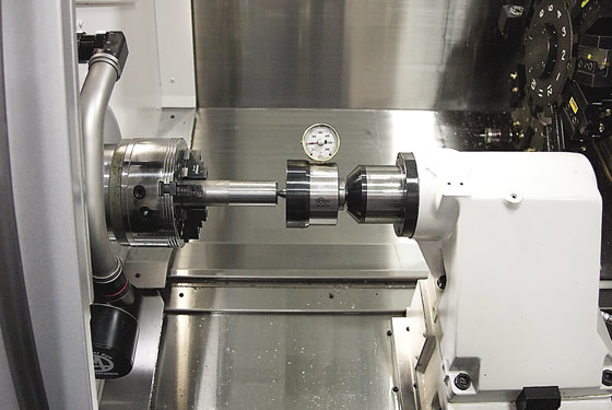
Figure 5. An analog force gage measures and displays the pounds of force applied by the machine’s tailstock.
While face driving delivers some real advantages, it is admittedly more complex than traditional chucking. Nevertheless, many shops have performed a cost/benefit analysis and concluded that face driving helps their bottom line in a variety of machining applications. CTE

About the Author: Mitchell Kirby is vice president of manufacturing for Riten Industries Inc., Washington Court House, Ohio. For more information about the company's standard and custom workholders, call (800) 338-0027 or visit www.riten.com.
Related Glossary Terms
- alloys
alloys
Substances having metallic properties and being composed of two or more chemical elements of which at least one is a metal.
- centers
centers
Cone-shaped pins that support a workpiece by one or two ends during machining. The centers fit into holes drilled in the workpiece ends. Centers that turn with the workpiece are called “live” centers; those that do not are called “dead” centers.
- chuck
chuck
Workholding device that affixes to a mill, lathe or drill-press spindle. It holds a tool or workpiece by one end, allowing it to be rotated. May also be fitted to the machine table to hold a workpiece. Two or more adjustable jaws actually hold the tool or part. May be actuated manually, pneumatically, hydraulically or electrically. See collet.
- feed
feed
Rate of change of position of the tool as a whole, relative to the workpiece while cutting.
- gang cutting ( milling)
gang cutting ( milling)
Machining with several cutters mounted on a single arbor, generally for simultaneous cutting.
- grinding
grinding
Machining operation in which material is removed from the workpiece by a powered abrasive wheel, stone, belt, paste, sheet, compound, slurry, etc. Takes various forms: surface grinding (creates flat and/or squared surfaces); cylindrical grinding (for external cylindrical and tapered shapes, fillets, undercuts, etc.); centerless grinding; chamfering; thread and form grinding; tool and cutter grinding; offhand grinding; lapping and polishing (grinding with extremely fine grits to create ultrasmooth surfaces); honing; and disc grinding.
- hard turning
hard turning
Single-point cutting of a workpiece that has a hardness value higher than 45 HRC.
- hardness
hardness
Hardness is a measure of the resistance of a material to surface indentation or abrasion. There is no absolute scale for hardness. In order to express hardness quantitatively, each type of test has its own scale, which defines hardness. Indentation hardness obtained through static methods is measured by Brinell, Rockwell, Vickers and Knoop tests. Hardness without indentation is measured by a dynamic method, known as the Scleroscope test.
- lathe
lathe
Turning machine capable of sawing, milling, grinding, gear-cutting, drilling, reaming, boring, threading, facing, chamfering, grooving, knurling, spinning, parting, necking, taper-cutting, and cam- and eccentric-cutting, as well as step- and straight-turning. Comes in a variety of forms, ranging from manual to semiautomatic to fully automatic, with major types being engine lathes, turning and contouring lathes, turret lathes and numerical-control lathes. The engine lathe consists of a headstock and spindle, tailstock, bed, carriage (complete with apron) and cross slides. Features include gear- (speed) and feed-selector levers, toolpost, compound rest, lead screw and reversing lead screw, threading dial and rapid-traverse lever. Special lathe types include through-the-spindle, camshaft and crankshaft, brake drum and rotor, spinning and gun-barrel machines. Toolroom and bench lathes are used for precision work; the former for tool-and-die work and similar tasks, the latter for small workpieces (instruments, watches), normally without a power feed. Models are typically designated according to their “swing,” or the largest-diameter workpiece that can be rotated; bed length, or the distance between centers; and horsepower generated. See turning machine.
- milling
milling
Machining operation in which metal or other material is removed by applying power to a rotating cutter. In vertical milling, the cutting tool is mounted vertically on the spindle. In horizontal milling, the cutting tool is mounted horizontally, either directly on the spindle or on an arbor. Horizontal milling is further broken down into conventional milling, where the cutter rotates opposite the direction of feed, or “up” into the workpiece; and climb milling, where the cutter rotates in the direction of feed, or “down” into the workpiece. Milling operations include plane or surface milling, endmilling, facemilling, angle milling, form milling and profiling.
- shaping
shaping
Using a shaper primarily to produce flat surfaces in horizontal, vertical or angular planes. It can also include the machining of curved surfaces, helixes, serrations and special work involving odd and irregular shapes. Often used for prototype or short-run manufacturing to eliminate the need for expensive special tooling or processes.
- spindle adapter
spindle adapter
Bushing or toolholder that permits affixing a variety of taper- and straight-shank tools to a machine spindle.
- tool steels
tool steels
Group of alloy steels which, after proper heat treatment, provide the combination of properties required for cutting tool and die applications. The American Iron and Steel Institute divides tool steels into six major categories: water hardening, shock resisting, cold work, hot work, special purpose and high speed.
- total indicator runout ( TIR)
total indicator runout ( TIR)
Combined variations of all dimensions of a workpiece, measured with an indicator, determined by rotating the part 360°.
- turning
turning
Workpiece is held in a chuck, mounted on a face plate or secured between centers and rotated while a cutting tool, normally a single-point tool, is fed into it along its periphery or across its end or face. Takes the form of straight turning (cutting along the periphery of the workpiece); taper turning (creating a taper); step turning (turning different-size diameters on the same work); chamfering (beveling an edge or shoulder); facing (cutting on an end); turning threads (usually external but can be internal); roughing (high-volume metal removal); and finishing (final light cuts). Performed on lathes, turning centers, chucking machines, automatic screw machines and similar machines.