Dear Doc: I attended your class and know you’re a strong believer in using a +0.8 unidirectional speed ratio during rotary dressing. However, some of our shop-floor people still insist on dressing anti-directional. How can I convince them?
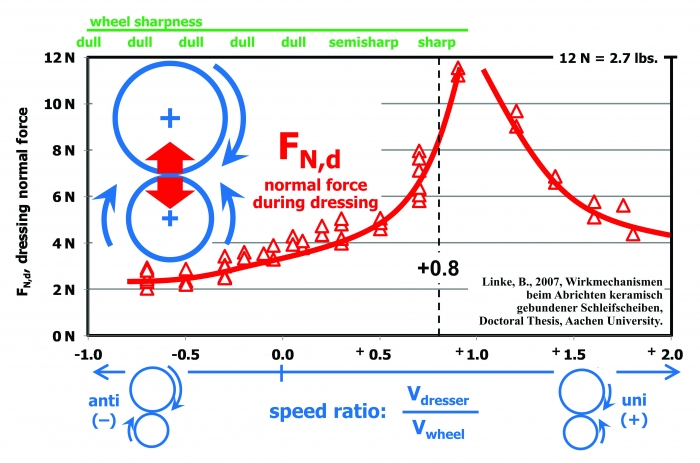
The Doc Replies: First, the speed ratio is the surface velocity of the dressing roll divided by the surface velocity of the grinding wheel. (That’s surface velocity, not rpm.) Anti-directional uses a negative sign (see the figure), and unidirectional uses a positive sign. For example, if your dressing roll is going 12,000 sfm in the clockwise direction and your grinding wheel is going 16,000 sfm in the counterclockwise direction, your speed ratio is +0.75. I strongly recommend being in the ballpark of +0.8, especially for those working in the aerospace industry, where grinding burn must be avoided at all costs. This will provide a sharp-dressed grinding wheel.
Typically, people still like to dress anti-directional for two reasons.
First, anti-directional will impart a finer surface finish because all those dull-dressed grits polish the workpiece. If the grit size in the wheel is too large, operators have no choice but to dress the wheel dull by going anti-directional. Unfortunately, this creates a lot more grinding heat. Here, switch to a finer-grit wheel and go unidirectional. I’ve eliminated lots of grinding burn this way.
Second, anti-directional will exert a smaller normal force during dressing. If your dressing spindle isn’t stiff or you have a wide dressing roll or disc, you will get more deflection of the wheel spindle and the dressing spindle. Even worse, you’ll have a bigger risk of chatter during dressing. In other words, the dressing spindle starts vibrating uncontrollably. When this happens, you’ll hear the dresser moaning, whining and screaming in protest. Operators then switch to anti-directional, and the moaning disappears—but the grinding burn begins.
The figure shows the measured normal force acting on the dressing spindle during dressing, based on the speed ratio. As we get closer and closer to Vdresser/Vwheel = +1.0, the dressing forces increase drastically. This causes the vibration and moaning.
But I don’t want you to dress anti-directionally, because that creates a dull wheel, which causes grinding burn, grinding chatter, excessive part deflection and longer cycle times when grinders start slowing down feed rates to cope.
So what’s the solution? It’s usually a trade-off. Dress with a +0.4 ratio. Your wheel won’t be quite as sharp, but your dressing forces will be cut in half—and hopefully the screaming will go away.
If you’re using a traverse disc, switch to a thinner disc. That will also reduce the normal force.
Also, some operators use anti-directional because they can dress in a new wheel more quickly. Imagine taking 1.0" off the diameter of a new wheel to put in a form. That dress-in takes a long time. Switching from Vdresser/Vwheel = +0.8 to Vdresser/Vwheel = -1.0 will cut your forces by a factor of four, meaning you can dress at four times the feed rate.
But this will give you a dull wheel. The solution? Dress in the wheel at -1.0, leave 0.004", and then dress in that last 0.004" with a +0.8 ratio. You’ll be able to dress superfast and also get a sharp wheel for grinding. The best of both worlds. Try it.
Related Glossary Terms
- chatter
chatter
Condition of vibration involving the machine, workpiece and cutting tool. Once this condition arises, it is often self-sustaining until the problem is corrected. Chatter can be identified when lines or grooves appear at regular intervals in the workpiece. These lines or grooves are caused by the teeth of the cutter as they vibrate in and out of the workpiece and their spacing depends on the frequency of vibration.
- dressing
dressing
Removal of undesirable materials from “loaded” grinding wheels using a single- or multi-point diamond or other tool. The process also exposes unused, sharp abrasive points. See loading; truing.
- feed
feed
Rate of change of position of the tool as a whole, relative to the workpiece while cutting.
- grinding
grinding
Machining operation in which material is removed from the workpiece by a powered abrasive wheel, stone, belt, paste, sheet, compound, slurry, etc. Takes various forms: surface grinding (creates flat and/or squared surfaces); cylindrical grinding (for external cylindrical and tapered shapes, fillets, undercuts, etc.); centerless grinding; chamfering; thread and form grinding; tool and cutter grinding; offhand grinding; lapping and polishing (grinding with extremely fine grits to create ultrasmooth surfaces); honing; and disc grinding.
- grinding wheel
grinding wheel
Wheel formed from abrasive material mixed in a suitable matrix. Takes a variety of shapes but falls into two basic categories: one that cuts on its periphery, as in reciprocating grinding, and one that cuts on its side or face, as in tool and cutter grinding.
- grit size
grit size
Specified size of the abrasive particles in grinding wheels and other abrasive tools. Determines metal-removal capability and quality of finish.
Author

Jeffrey A. Badger, Ph.D., is an independent grinding expert. He will be giving his 3-day High Intensity Grinding Course from Sept. 26-28 in Columbia, S.C., hosted by S.L. Munson. Visit www.thegrindingdoc.com for details. He can be reached by phone at 512-934-1857 or via email at [email protected].