The tagging applications for radio frequency identification (RFID) are vast, including pets, property—and even people. Recently, Micro-Mechanics Inc., a Morgan Hill, Calif., machine shop, worked with process control equipment provider Caron Engineering Inc., Wells, Maine, to implement an RFID tagging system on its Okuma LB series CNC lathe.
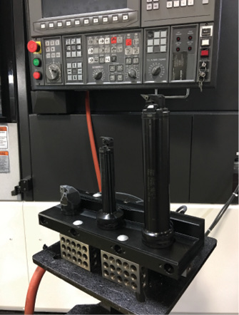
The RFID read-station on Micro-Mechanics’ Okuma lathe transfers tool offset and usage data directly to the machine control. Image courtesy Micro-Mechanics.
Micro-Mechanics is no newcomer to RFID. Company president Chris Borch and his team began “reinventing” the shop 5 years ago after installing several Makino horizontal machining cells with Makino’s Modular Machining Complex (MMC2) technology and integrating them with RFID readers. Since then, the shop has rolled the technology out to every part of the shop. “Nothing hits the floor unless it’s been preset, tagged and simulated ahead of time,” Borch said.
Its latest addition is a Tool Connect system from Caron Engineering, which reportedly is a simple, cost-effective way to automate the transfer of data from a presetter to a machine control. The system at Micro-Mechanics uses an RFID chip epoxied into Sandvik Coromant Capto quick-change toolholders.
Micro-Mechanics presets each tool offline and writes the X-axis offset, or tool diameter, for milling cutters and tool length (Z-axis offset) to the chip with the push of a button. Once at the machine, the tools are individually loaded into a cradle, which reads the offset and other tool data, such as the expected tool life, and sends it to the control. The operator then places the tool in the appropriate turret position before moving to the next tool.
Ryan Hegman, national sales manager at Caron Engineering, emphasized the high level of accuracy Tool Connect provides. “The data comes directly from the presetter,” he said. “This not only eliminates the chance of operator error, but significantly reduces setup time. Another very important point is the ability to automatically keep track of tool life. Because the system updates each tool with usage data upon removal from the machine, maximum utilization of cutting tools is assured.”
Borch agreed. He said the machine uptime percentage at Micro-Mechanics is in the high 90s, and setup time went from several hours to 5 minutes. This is quite an achievement when you consider that Micro-Mechanics is a high-mix, low-volume shop that makes parts for the aerospace, semiconductor and medical industries. “If suppliers are interested in developing a controlled machining process, then one of the first and most important steps is RFID tool management,” Borch said. “The technology itself is quite simple—you’re just reading and writing data. But it’s a very important piece of a complete digital manufacturing solution.”
Related Glossary Terms
- computer numerical control ( CNC)
computer numerical control ( CNC)
Microprocessor-based controller dedicated to a machine tool that permits the creation or modification of parts. Programmed numerical control activates the machine’s servos and spindle drives and controls the various machining operations. See DNC, direct numerical control; NC, numerical control.
- gang cutting ( milling)
gang cutting ( milling)
Machining with several cutters mounted on a single arbor, generally for simultaneous cutting.
- lathe
lathe
Turning machine capable of sawing, milling, grinding, gear-cutting, drilling, reaming, boring, threading, facing, chamfering, grooving, knurling, spinning, parting, necking, taper-cutting, and cam- and eccentric-cutting, as well as step- and straight-turning. Comes in a variety of forms, ranging from manual to semiautomatic to fully automatic, with major types being engine lathes, turning and contouring lathes, turret lathes and numerical-control lathes. The engine lathe consists of a headstock and spindle, tailstock, bed, carriage (complete with apron) and cross slides. Features include gear- (speed) and feed-selector levers, toolpost, compound rest, lead screw and reversing lead screw, threading dial and rapid-traverse lever. Special lathe types include through-the-spindle, camshaft and crankshaft, brake drum and rotor, spinning and gun-barrel machines. Toolroom and bench lathes are used for precision work; the former for tool-and-die work and similar tasks, the latter for small workpieces (instruments, watches), normally without a power feed. Models are typically designated according to their “swing,” or the largest-diameter workpiece that can be rotated; bed length, or the distance between centers; and horsepower generated. See turning machine.
- milling
milling
Machining operation in which metal or other material is removed by applying power to a rotating cutter. In vertical milling, the cutting tool is mounted vertically on the spindle. In horizontal milling, the cutting tool is mounted horizontally, either directly on the spindle or on an arbor. Horizontal milling is further broken down into conventional milling, where the cutter rotates opposite the direction of feed, or “up” into the workpiece; and climb milling, where the cutter rotates in the direction of feed, or “down” into the workpiece. Milling operations include plane or surface milling, endmilling, facemilling, angle milling, form milling and profiling.
- process control
process control
Method of monitoring a process. Relates to electronic hardware and instrumentation used in automated process control. See in-process gaging, inspection; SPC, statistical process control.
Author

Kip Hanson is a contributing editor for Cutting Tool Engineering magazine. Contact him by phone at (520) 548-7328 or via e-mail at [email protected].